
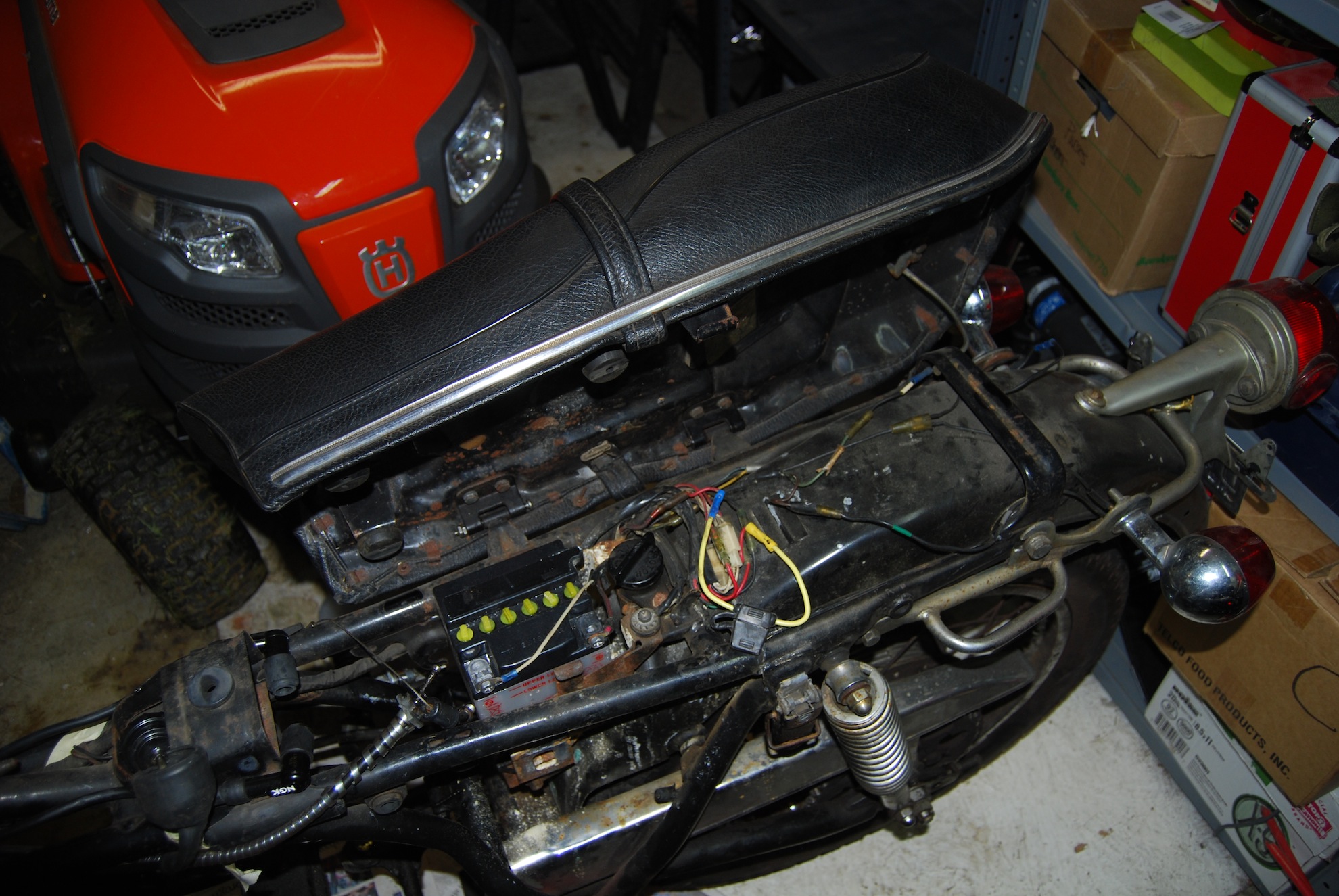
Seat Removal
The 75 RD250 has a hinged seat, under which you will find the battery, fill tube for the oil tank, fused lines and an assortment of other wiring. It’s held in place by two hinge bolts that should also have cotter pins installed. In my case, only one was the original bolt w/ cotter pin, the other was just a bolt and a couple of nuts. The mechanism that holds the seat in the open position is a small metal rod that is inserted into a slot on the rear portion of the frame. When opened, the large end of the rod falls into a valley in the slot of the frame, keeping it held in place. Once the hinge pins are removed, it’s easy enough to maneuver the locking mechanism out of the frame and lift the whole seat off.
-
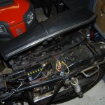
- Opened Seat
-
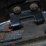
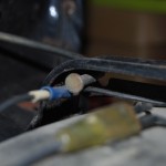
- Hinge bolt and cotter pin
-
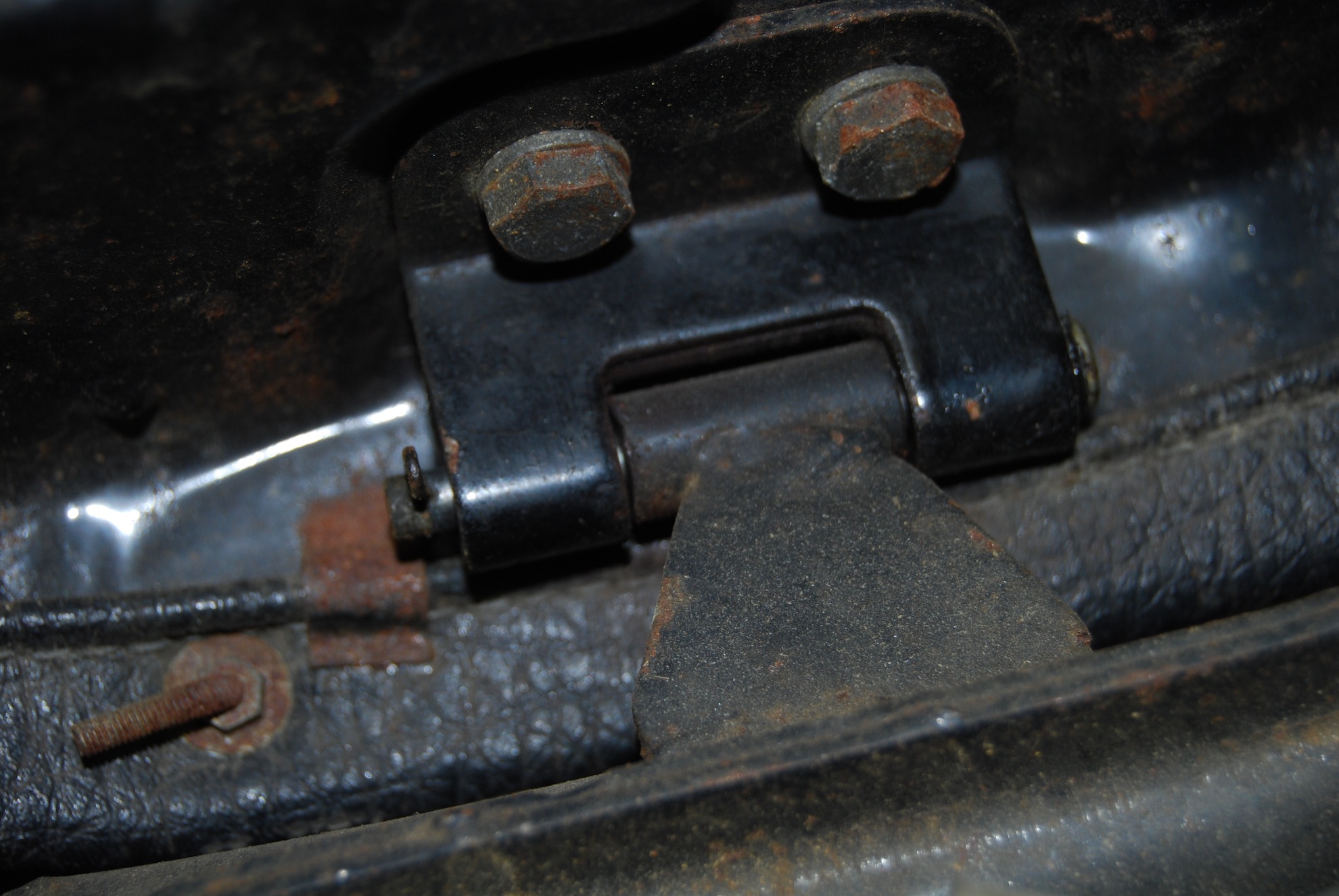
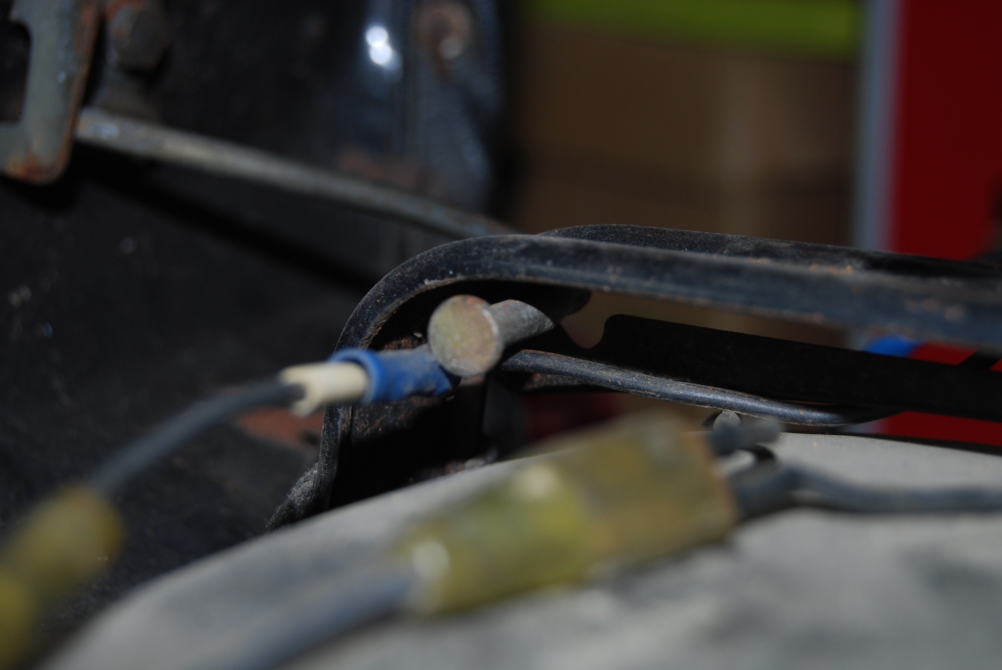
- Closeup of locking mechanism
Headlamp and Wiring Removal (INTO THE RATS NEST!!)
I was absolutely stunned at how much wiring was crammed into the space behind the headlamp reflector. Be prepared to take good notes if you’re going to tackle this and try to get it all back together. First, there’s a small retaining screw on the bottom right (from the riders POV) of the headlamp assembly. Unscrew this to allow the reflector to be pulled free, and to expose the glorious wiring mess underneath.
-
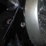
- Headlamp retention screw

-
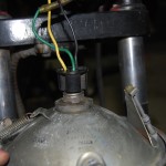
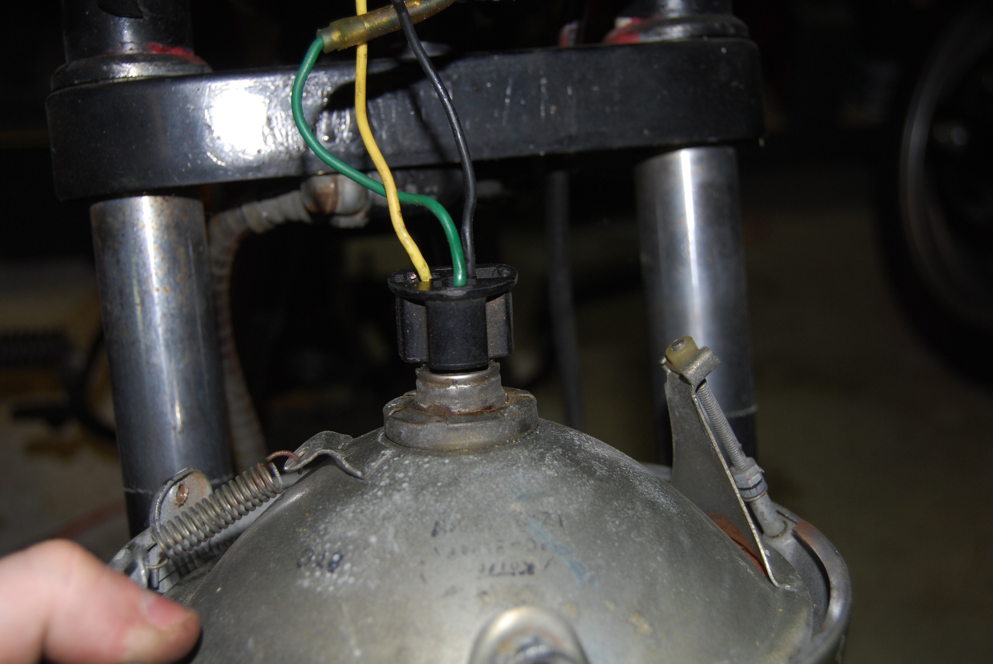
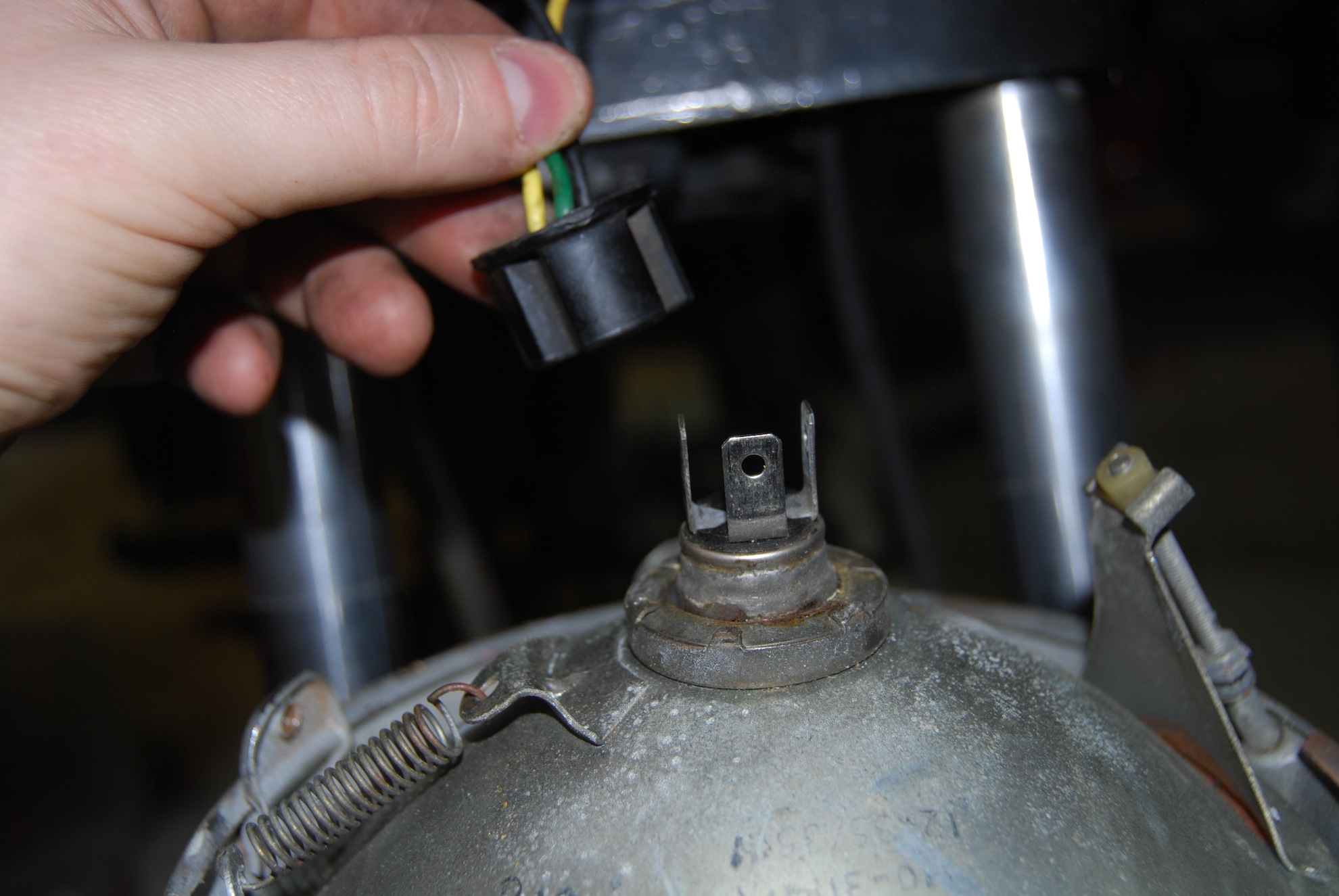
- Reflector and headlamp plug
Enter the giant rats nest:

First, I removed the plug from the rear of the headlamp reflector.
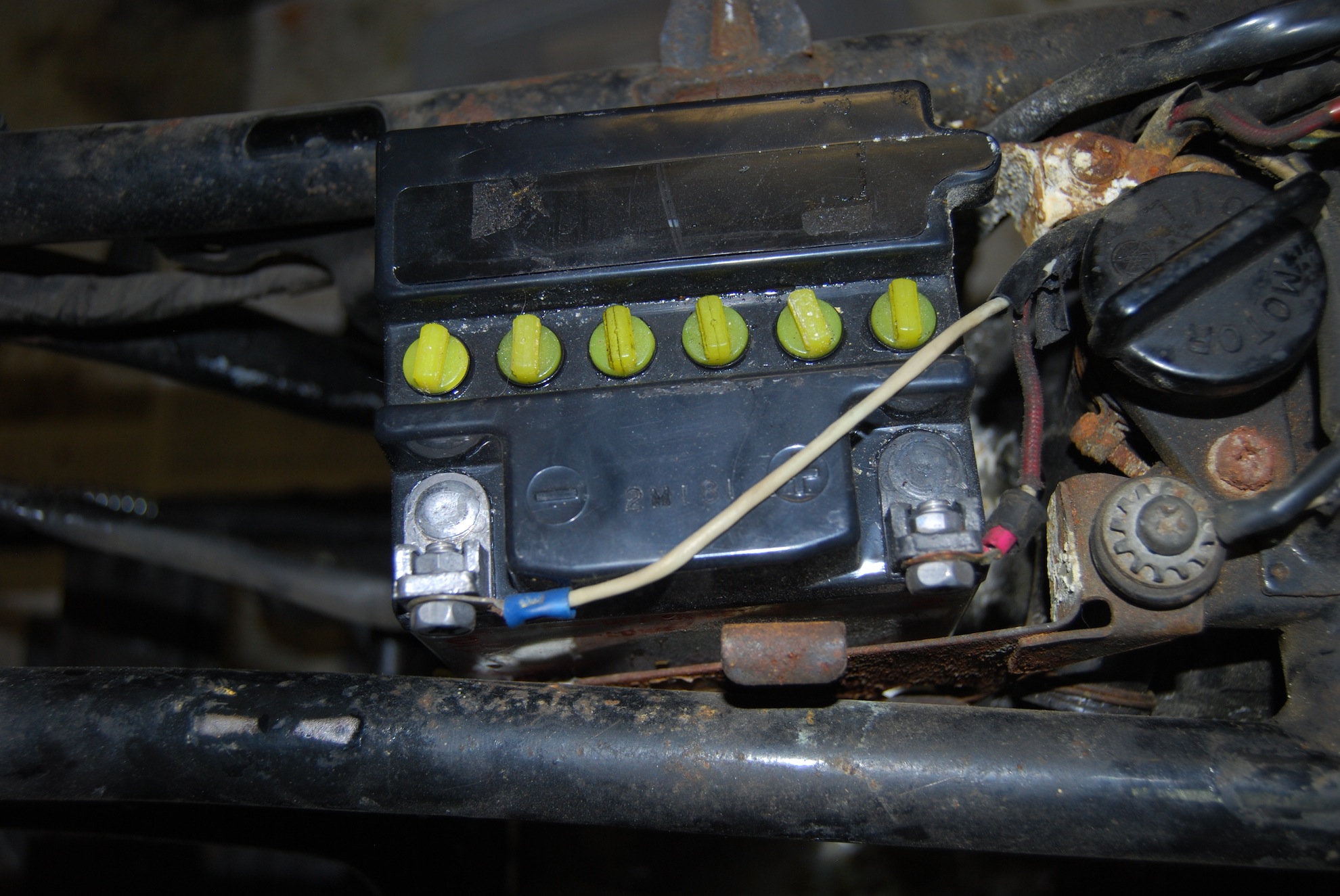
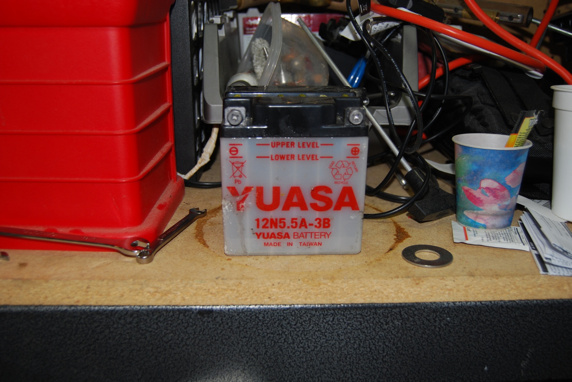
Then, I realized some of these lines may still be energized. Always good practice to remove the power source before working on the electrical system, so next task was to remove the battery. Just unscrew the positive and negative posts and pull the battery out. Careful not to spill any acid.
-
- Remove positive and negative leads
-
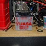
- Battery Removed
Strategy for Wiring Removal:
1) Take a ton of pictures. Even now, as I’m writing this, I have notes that say I don’t know where a certain wire was located, but looking at the pictures I took (nearly 60 for the whole process), I easily figured out where it was terminated.
2) There were 6 places that wires were coming from to be united behind the headlamp. Small and large bundles to center gauges, large bundle to back of bike (battery), bundle to Right controls, bundle to Left controls, and small 2 wire bundle to front brakes. I went though every wire from each of the 6 places individually, documenting where it came from, where it went, if there were hubs or splitters or other wires involved, etc.
3) In the end, I combined my notes and my pictures to create an overview of the junctions made behind the headlamp. In this step I went back and tried to fill in any blanks in my notes that I missed. I think I have a complete picture, but we’ll see what happens when I go to wire it all back up. Hopefully some new gauges lights will simplify at least some of it (maybe). A new harness may also be in order, some of those wires are looking pretty ragged.
Instead of going through the entire boring process of tracing wires, I’m going to put the picture I was able to draw off my notes and photos. I’m working on getting this into a more web-friendly format (some javascript or something). I have tons of pictures though, so if you’re in a jam wiring-wise, hit me up and I’ll send you them in an archive, maybe they’ll help.
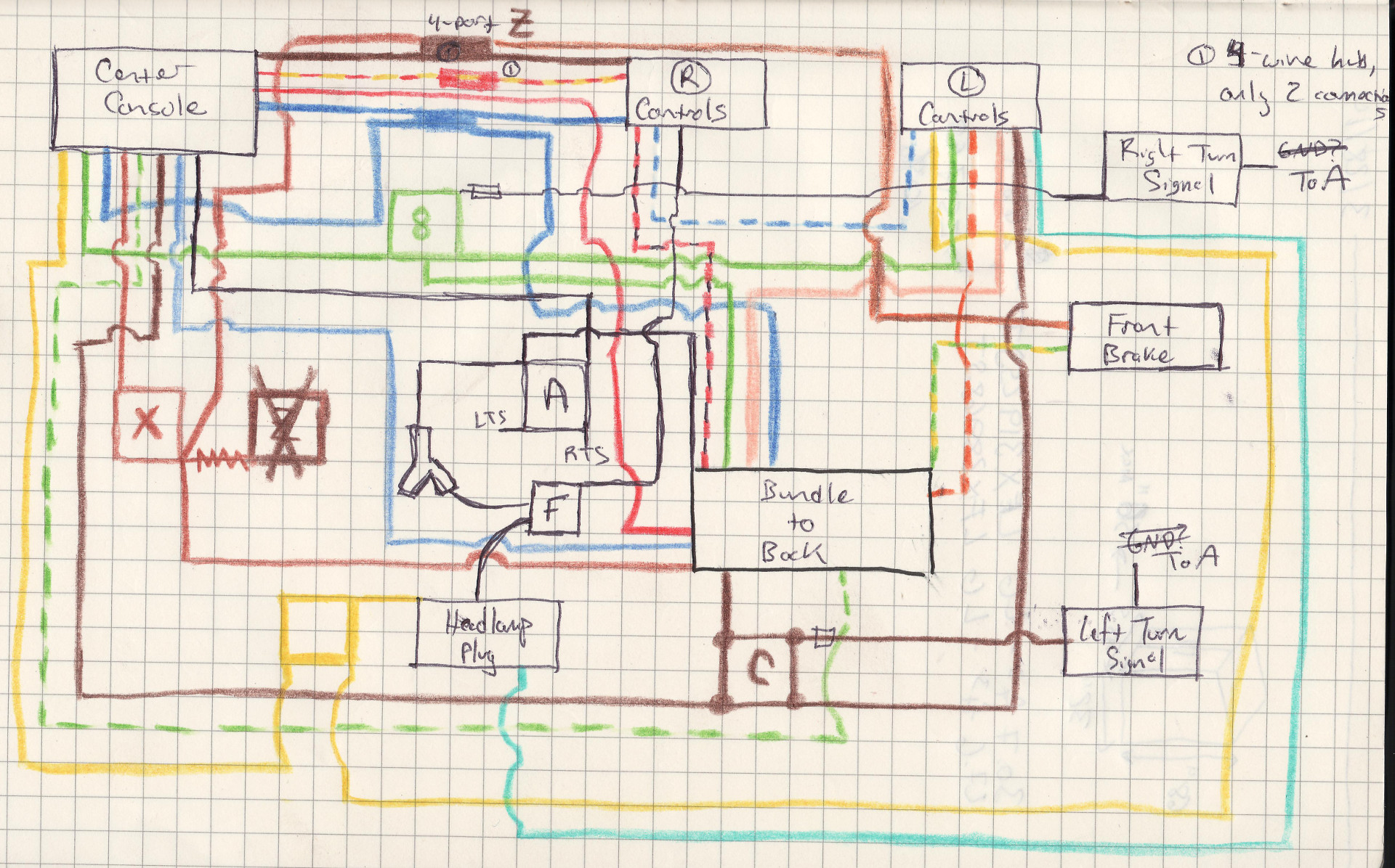
I know that’s probably not a very useful image, but until I get something better worked out, it’ll have to do.