
DISCLAIMER: This is going to be a lot of detailed tracing of the main harness. It’s probably interesting and very helpful to someone that needs to do the same or has a question about the process, but probably pretty monotonous for casual reading.
Last time I detailed (well, kind of) the removal of all the junctions that meet behind the headlamp. Actually, most of the details were left out, but I provided a diagram showing the junctions and each of the 6 places they could go (plus the Left and Right front turn signals). As a recap, here are the main bundles that come into the junction behind the headlamp:
-
- Right Controls Bundle
-
- Left Controls Bundle
-
- Large Bundle to Console
-
- Small bundle to console
-
- Large bundle to back (main harness)

-
- Small 2-wire bundle from from brakes

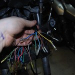
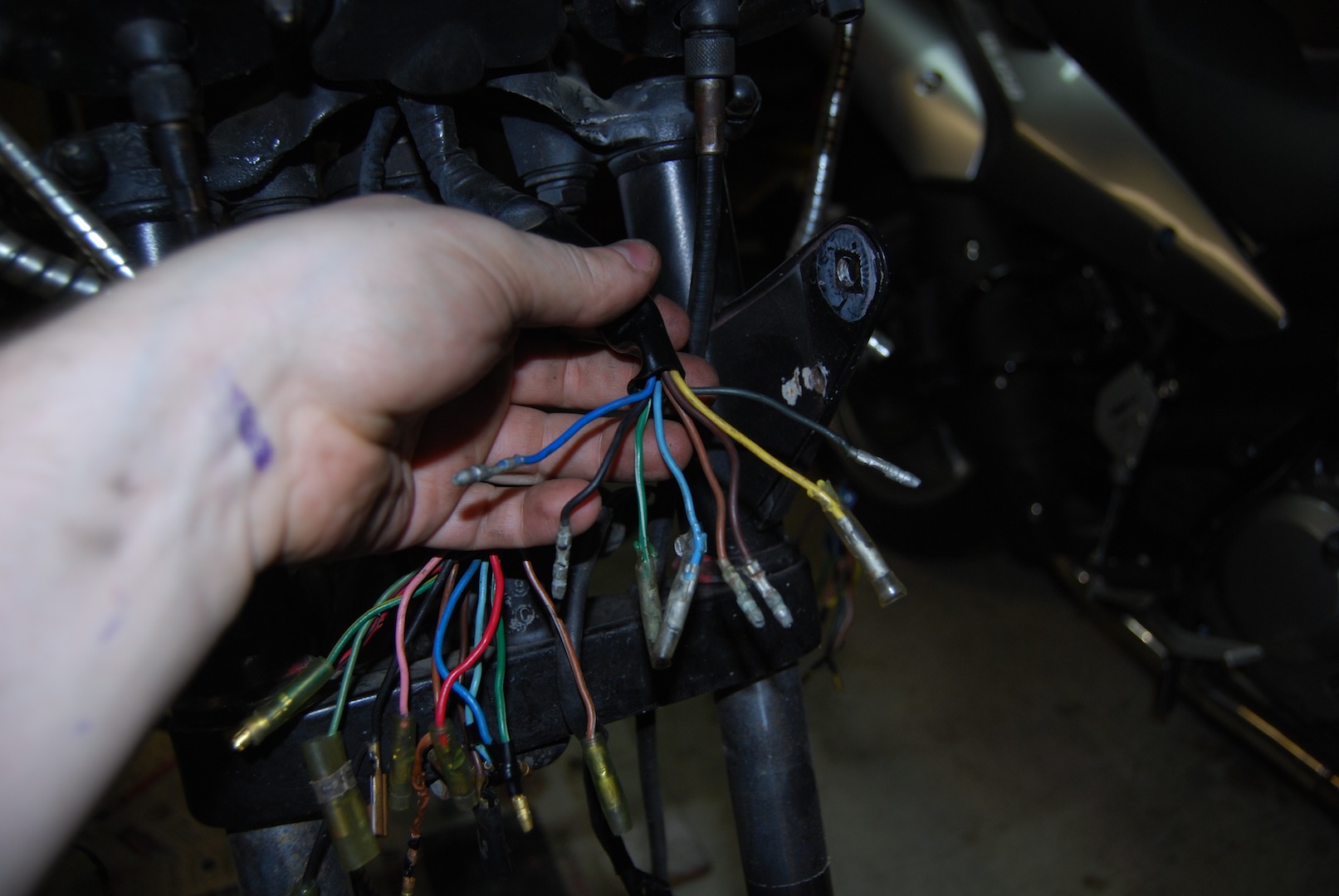
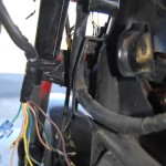
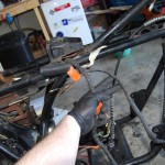
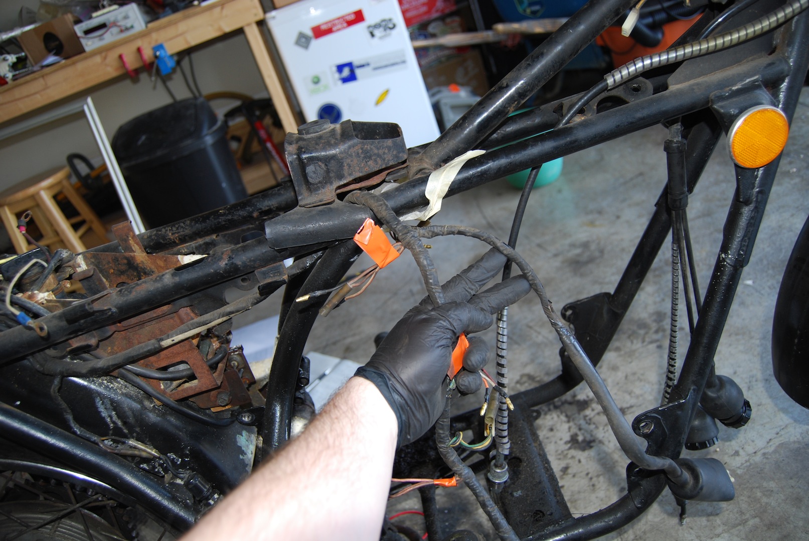
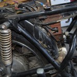
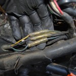
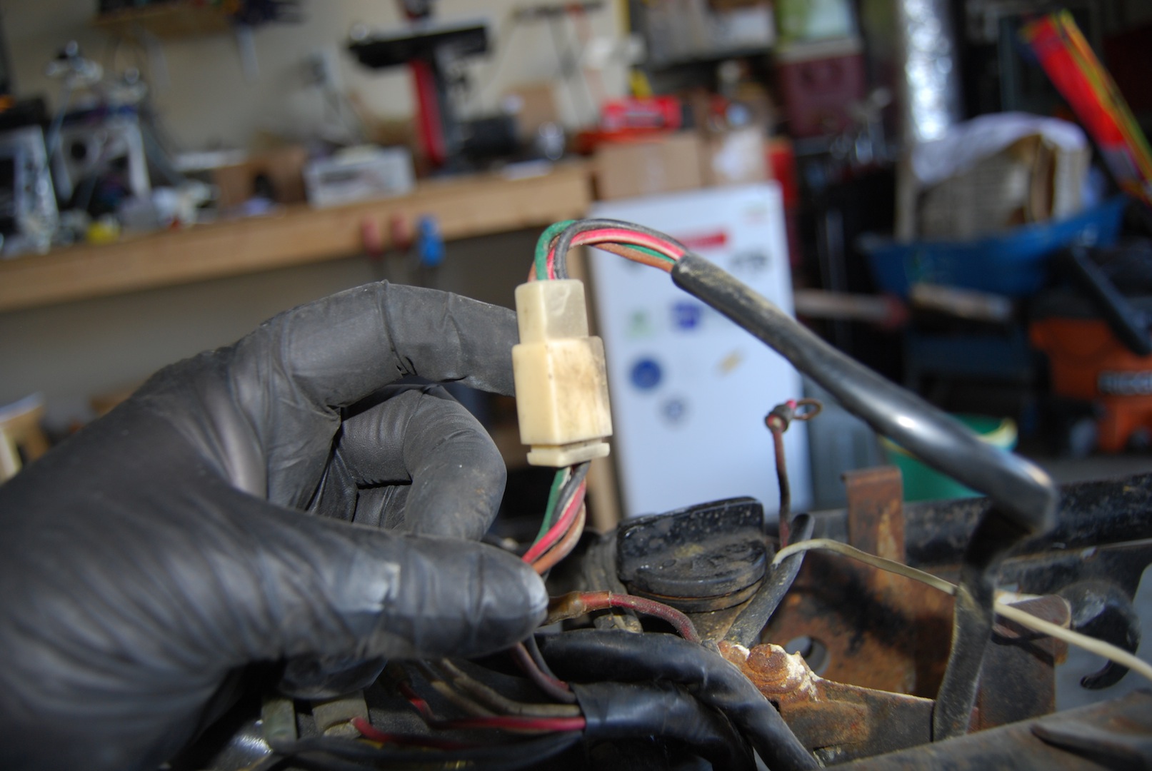
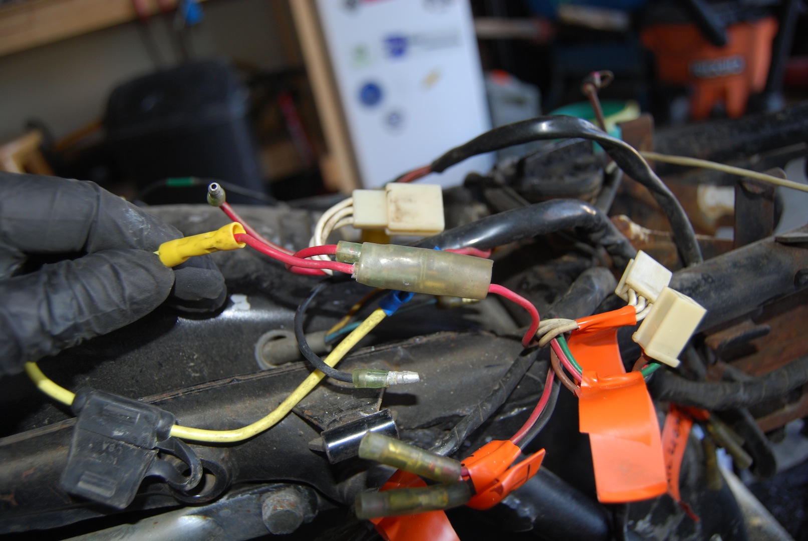
In this post, we’re focusing on the main harness, which connects functionality at the rear of the bike (rectifier/voltage regulator, battery, rear lamps, etc) to the controls at the front (indicators in gauges, hand controls, etc). Along the way there are connections for the ignition, lamp checker, and other items. We’ll detail stripping the main bundle from the headlamp bracket all the way back to the battery, then go over some of the things we can upgrade to make life in the future less of a headache.
Here’s another shot of the main harness. Notice the dangling headlamp connector, that can be removed.

Main harness portion behind headlamp
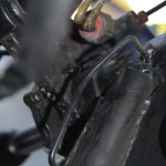
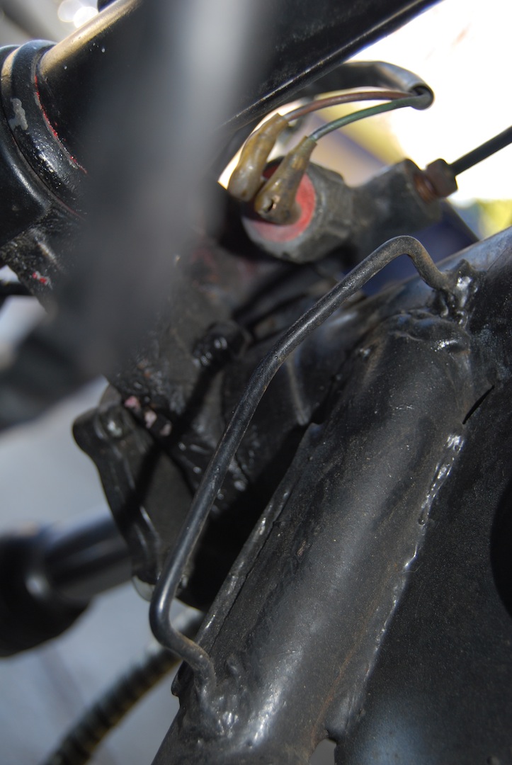
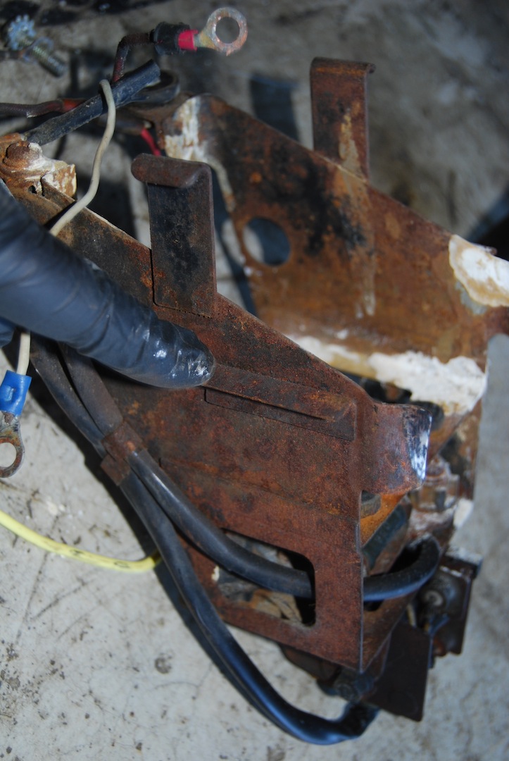
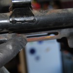
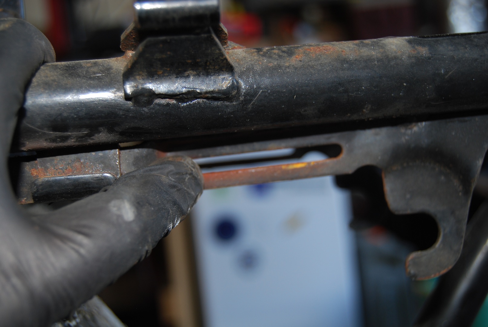
The main bundle runs through a big metal “D” bracket on the left side of the frame. Here are a couple of pics showing that location from the front and back:
-
- Harness through D bracket (front)
-
- Harness through D bracket (back)
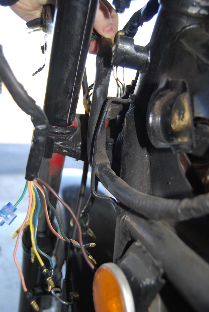
-
- Empty D bracket
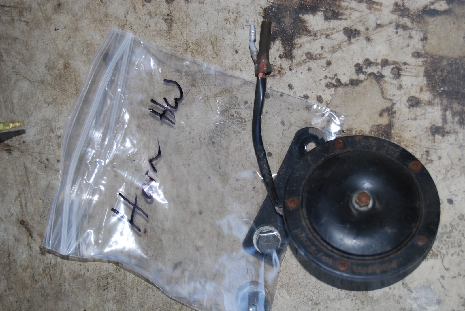
The first 3 wires coming off the main bundle as we work our way back are the horn wires. They were all orange on mine (at least I think they were, there was lots of grime). Unplug these and remove the horn, which is held in place by a single bracket. I removed it all. The horn bracket mounts via a single bolt to a frame bracket.
-
- Horn Wires
-
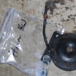
- Horn and horn HW
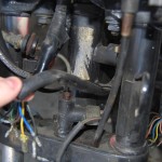
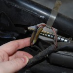
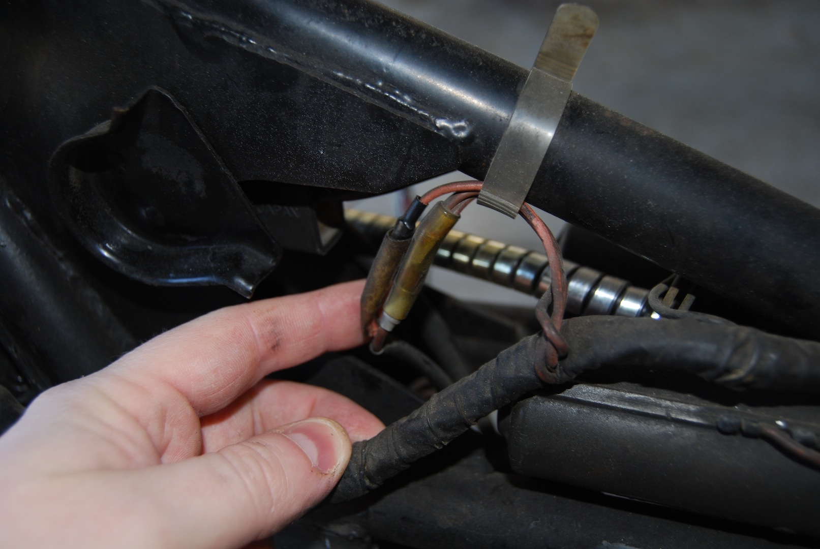
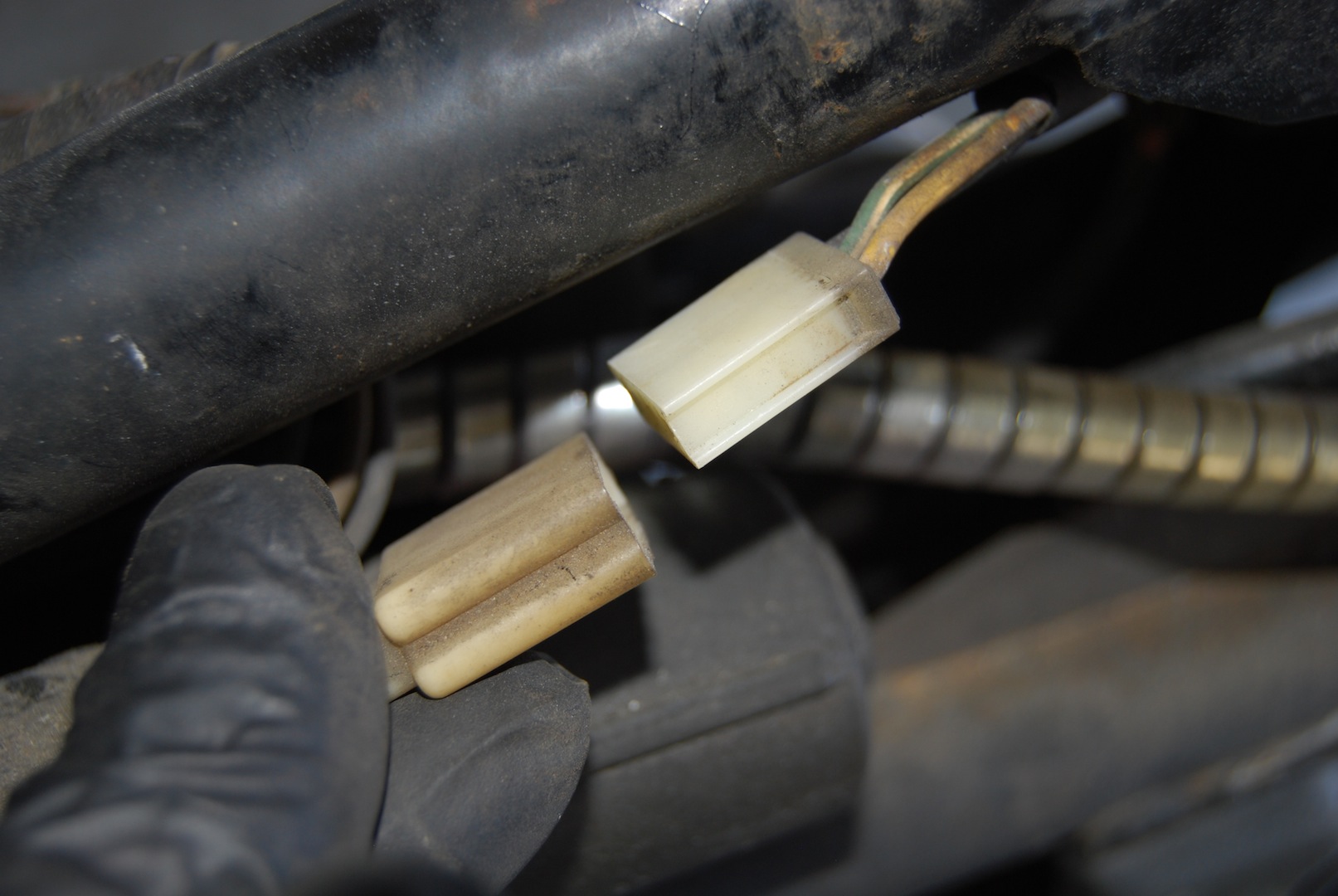
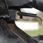
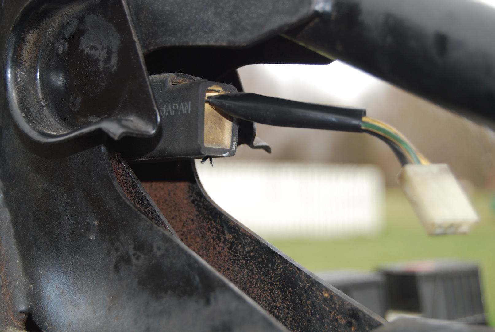
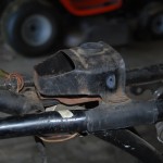
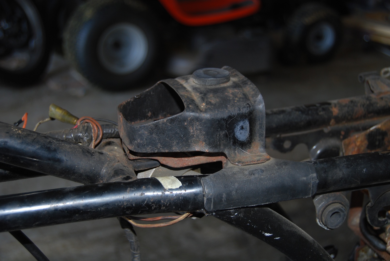
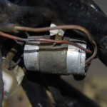
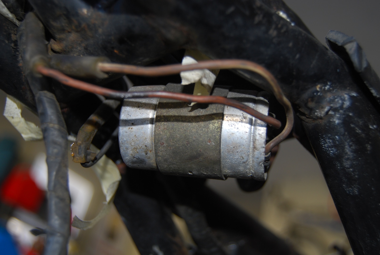
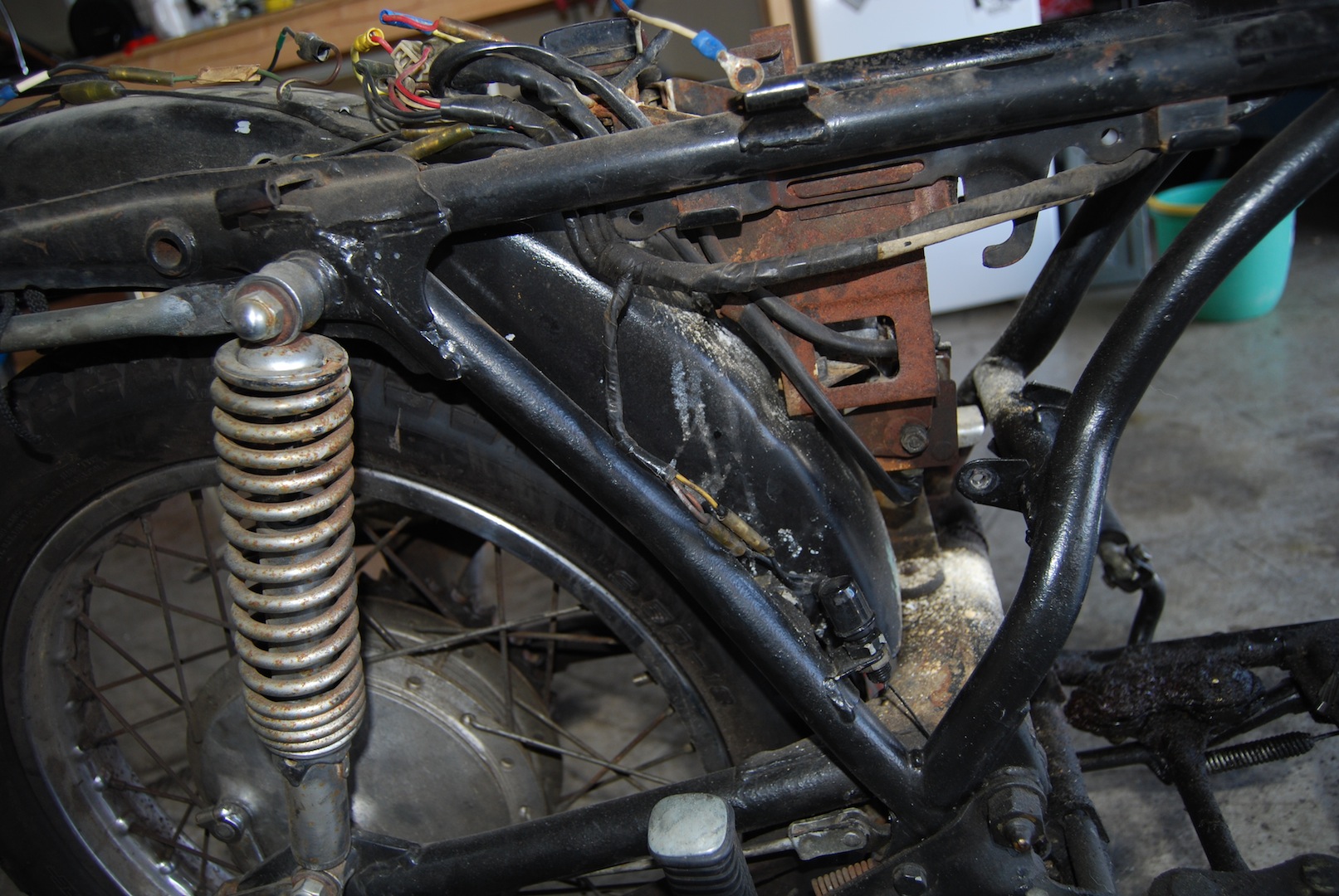
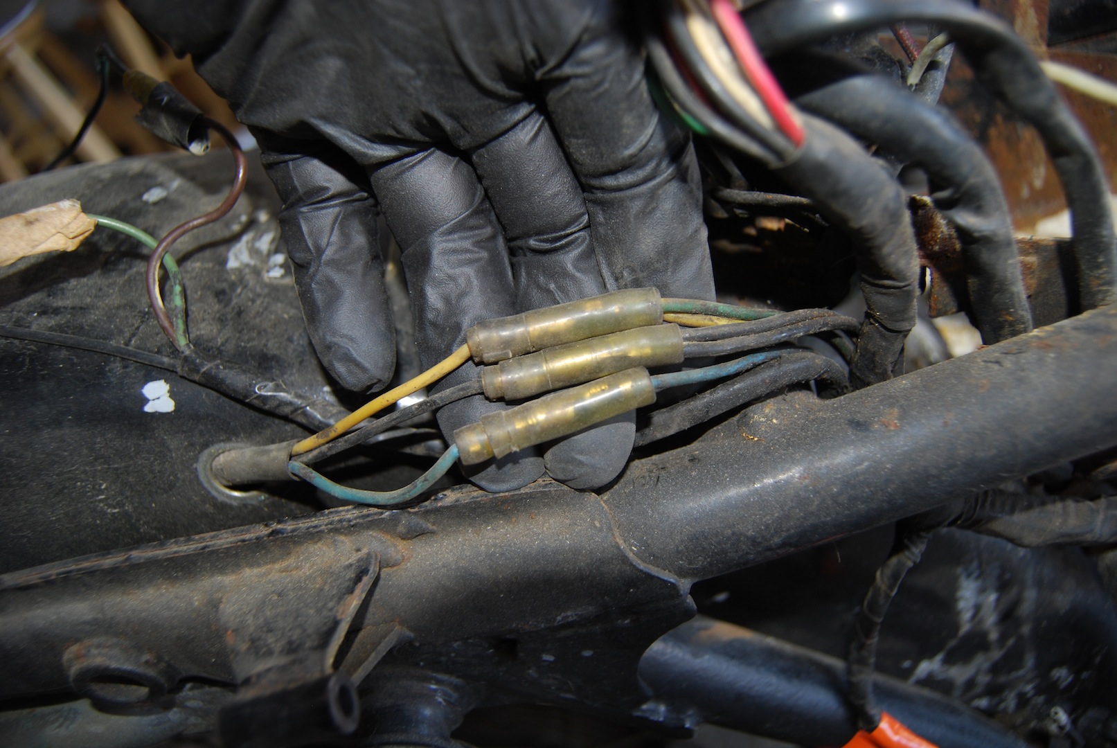
Next you’ll come to another 3 wire bundle coming off the main harness. Mine were colored black, yellow and green/white. These wires connected via a plug to a small, rubber-encased unit located under the frame near the front tank rests. It took me a while to figure it out, but this is the lamp checker. It was hard to remove the checker itself, I had to use some circlip pliers to pry the rubber on the top out so I could pull it free from its metal bracket. Don’t ask me what it does…
-
- Wires that run to lamp checker
-
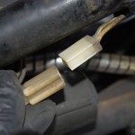
- Lamp checker unplugged
-
- Lamp checker
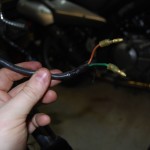
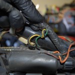
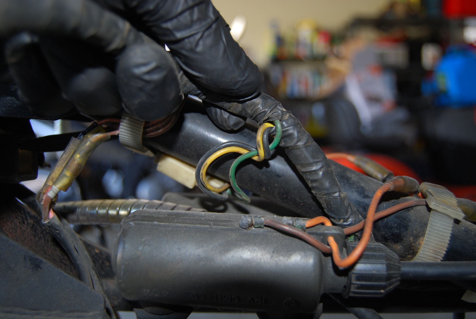
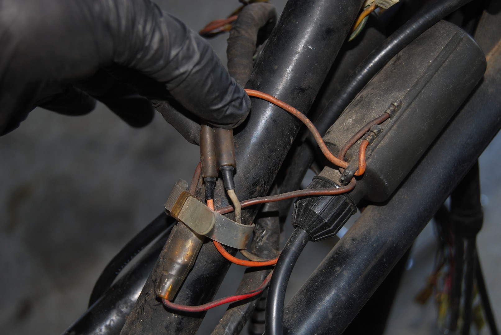
Next up the chain is another set of 3 wires, red/black, orange and white. This bundle goes to the ignition coils, which are mounted underneath the portion of the frame that the tank fits around. The red/black wire actually terminates into a “Y” connector, and the brownish male leads from both coils connect to the other end of this “Y”. The white cable from the harness connects to the orange cable of the coil on the right, while the orange cable connects to the orange cable from the left coil. I’m not sure if this matters or not, but I’d rather keep it like it was since I know that worked.
-
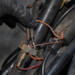
- Wires leading to coil
-
- Right coil
-
- Left coil
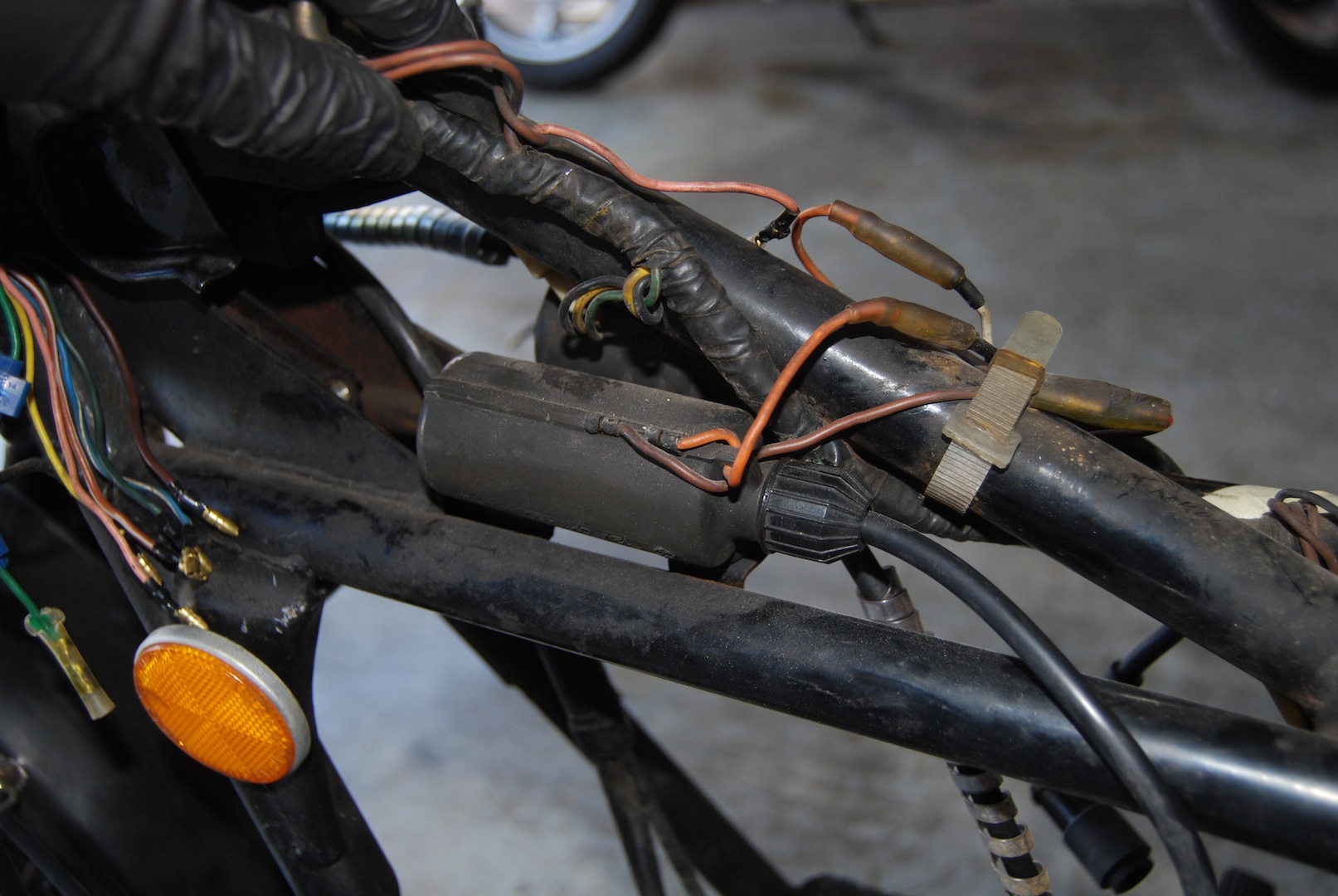
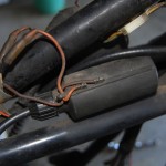
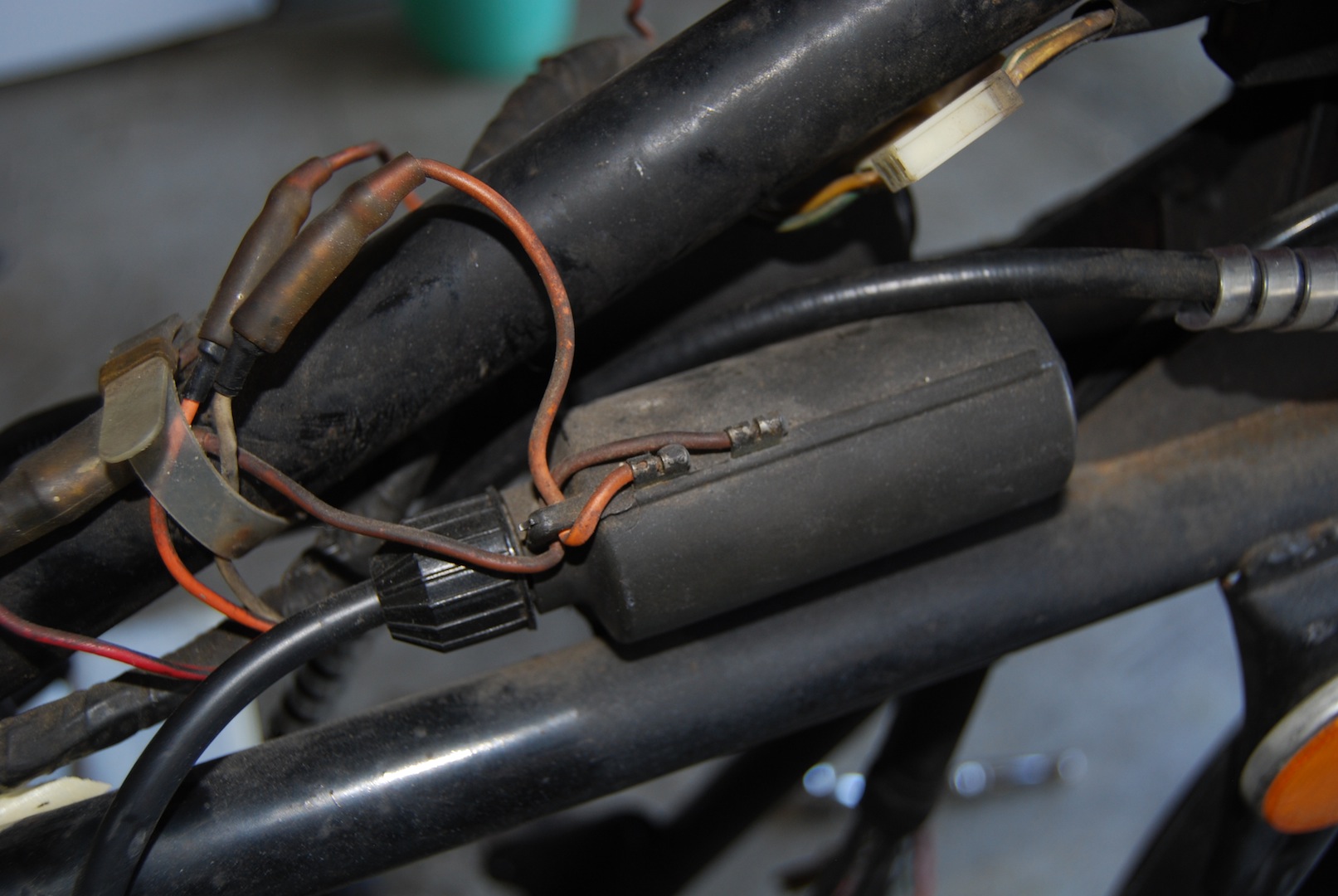
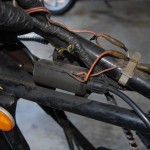
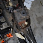
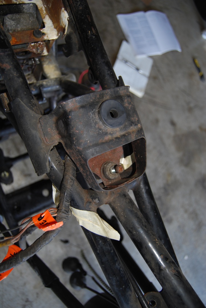
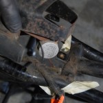
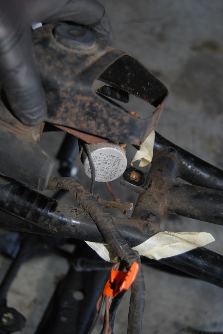
At this point, the whole harness passes under the frame bar, and as we’re going backwards, it passes from left to right. Near the rear rest where the tank meets the frame, you’ll find the flasher unit. 4 wires come off the harness and go to the flasher. They are brown/white, 2x brown, and a black wire. The 2x browns get combined, so the flasher only has 3 inputs (brown combined, brown/white and black).
-
- Rear tank mount and wires
-
- Flasher unit
Also near this area is the big bundle that goes down to the engine that I disconnected several posts ago.
-
- Bundle leading to engine (disconnected during engine removal)
-
- Notice that the engine bundle is across the bundle from the flasher wires
One bolt holds down the rear tank rest, and removing it will allow you to remove the flasher.
-
- Rear tank mount
-
- Rear tank mount removal (along with flasher)
Next comes a 3 wire bundle that goes down to the rear brake, colored 2x brown and yellow.
-
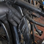
- Wires leading to rear brake
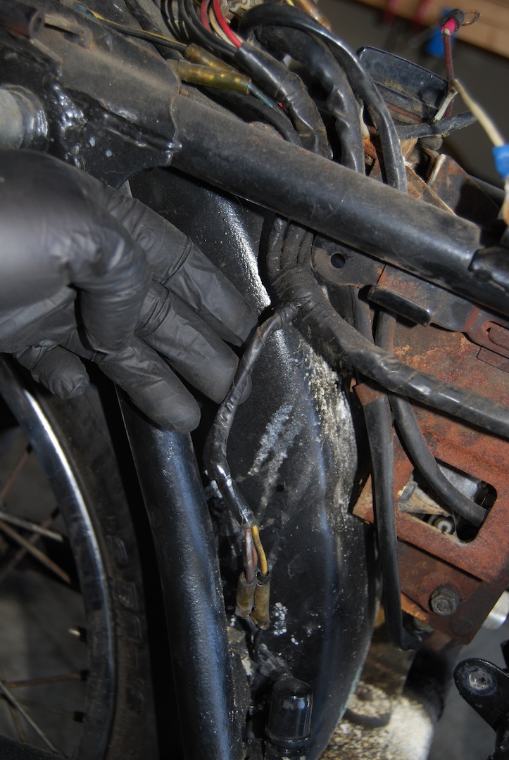
-
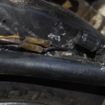
- Closeup
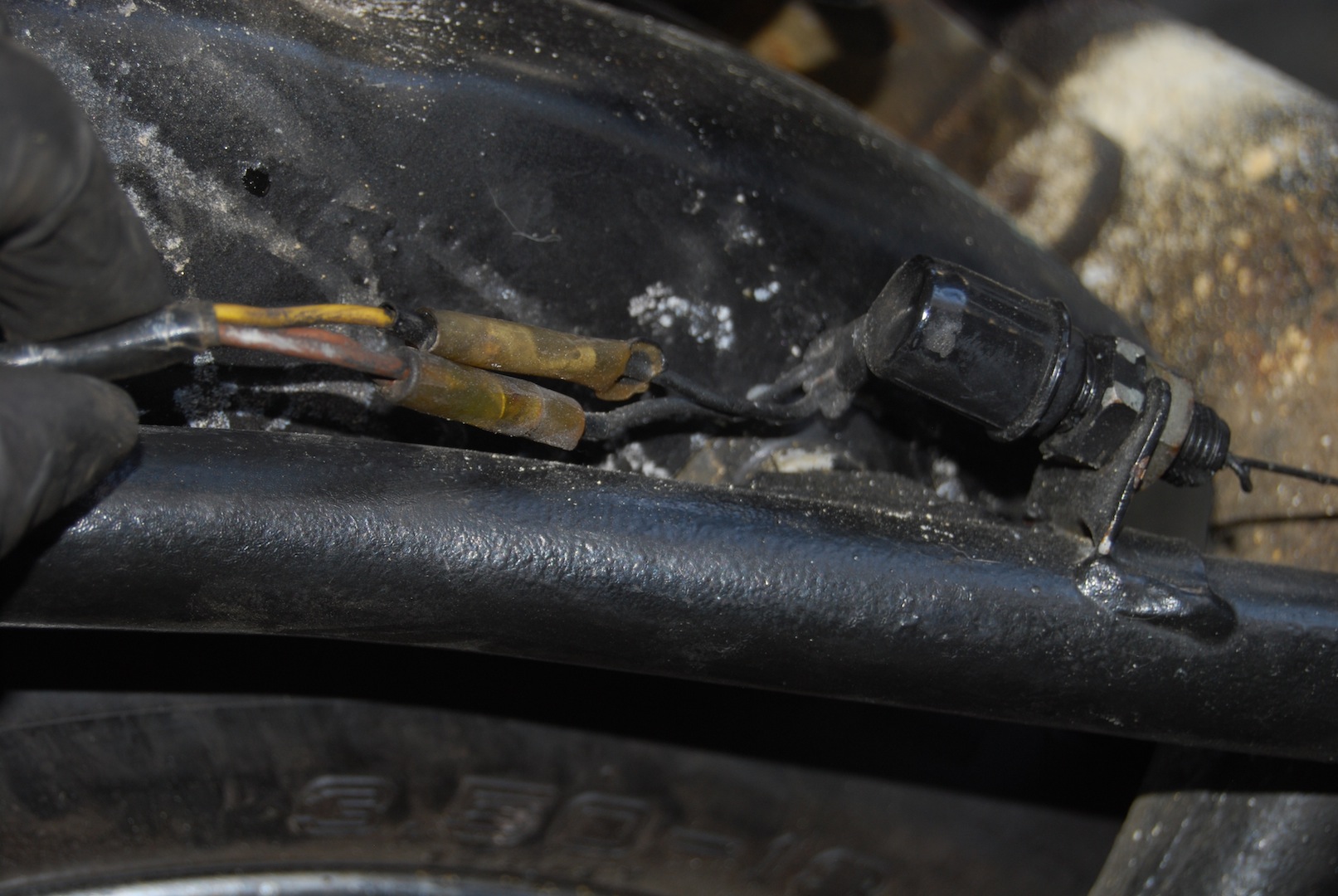
-
- Another view of rear brake wires
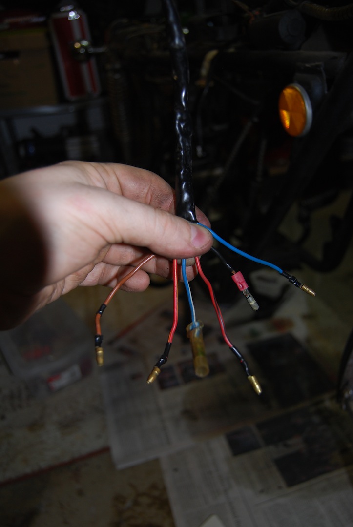
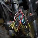
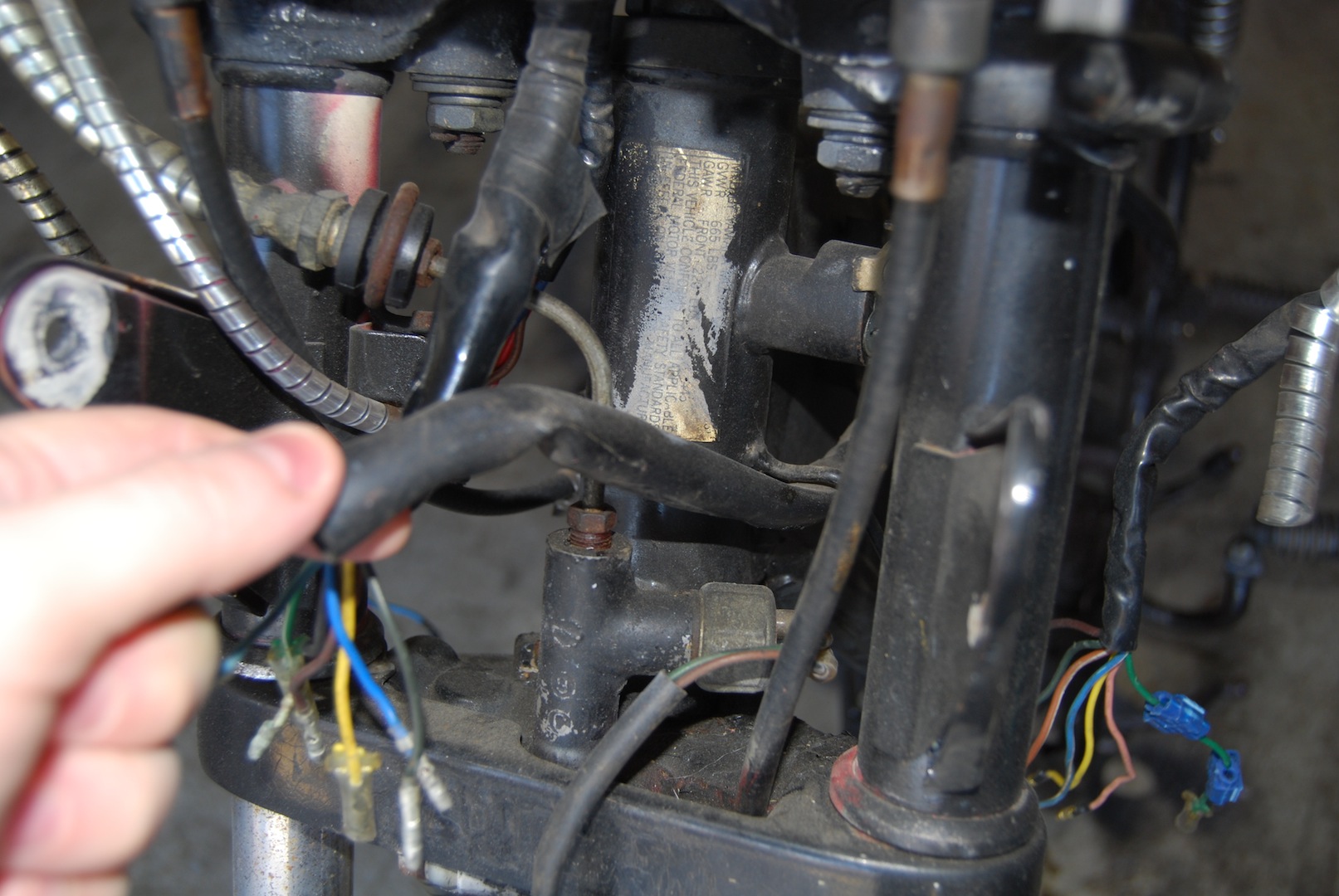
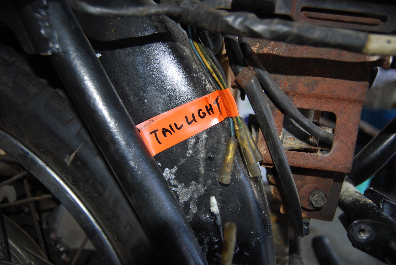
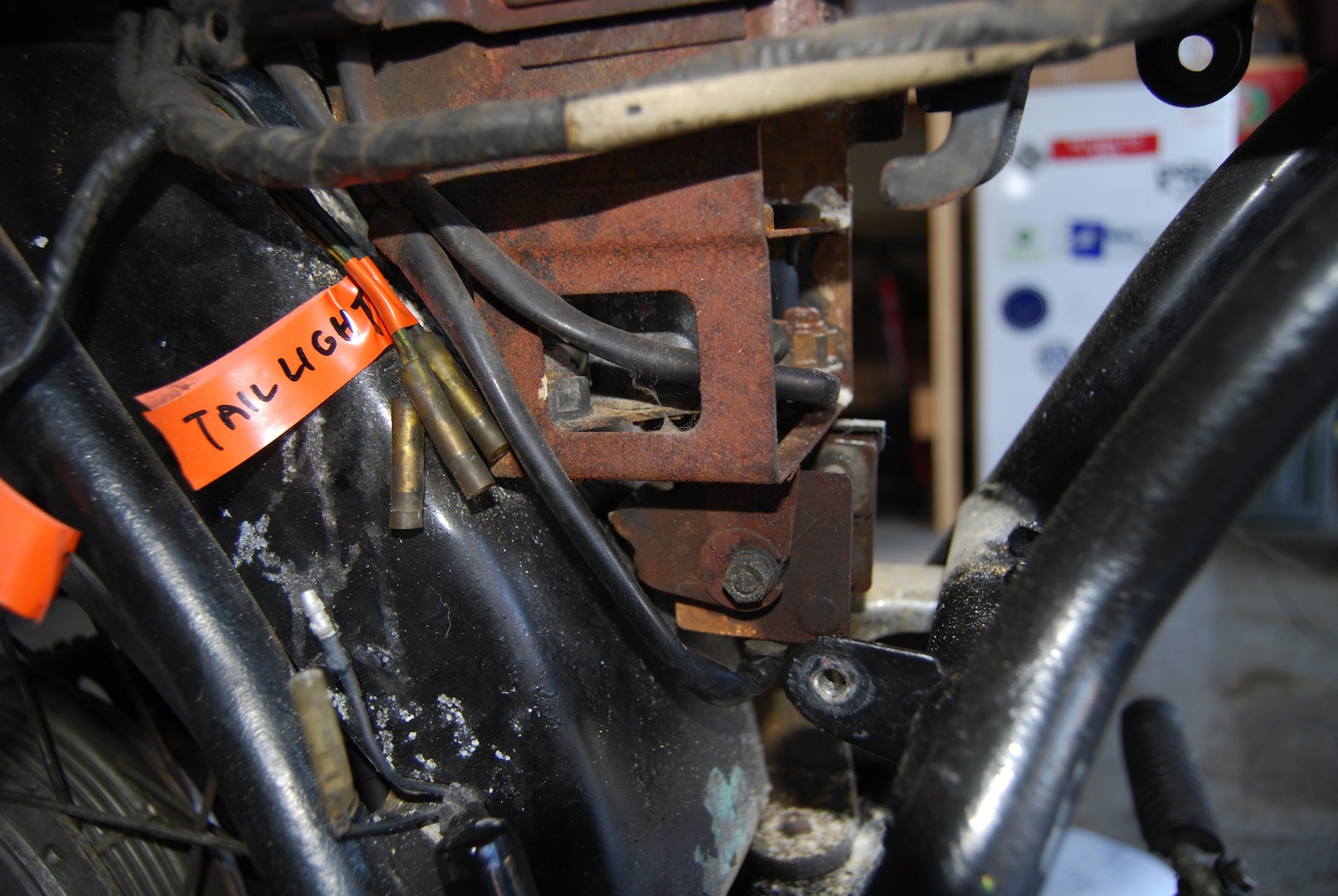
Near the end of the bundle, 5 wires come out and get combined down to three that go into a port in the rear fender, and on to the taillight. From the harness, we find separate green and yellow wires, which get combined, 2 blacks which get combined, and a solitary blue.
-
- Wires from harness (right) to taillight (left)
-
- Taillight wires labeled and disconnected
Near the junction for the taillight is another 3 wires, black, brown and green, that go to the turn signals. Acutally, it’s visible in the picture above showing the original taillight connection, in the left side of the picture. The black gets Y’d and goes to both signals, the green goes to the rear right signal, and the brown goes to the rear left. Sorry, no specific pictures of it.
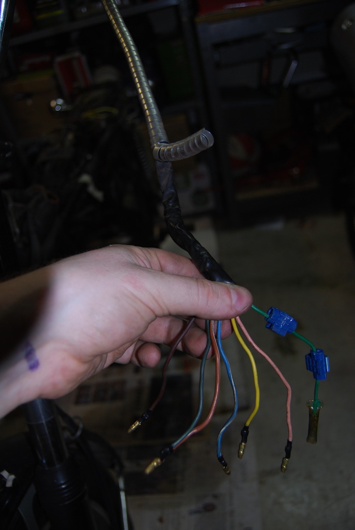
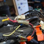
Almost there! There are 5 big connections at the very end of the main harness. Here they are, in all their glory:
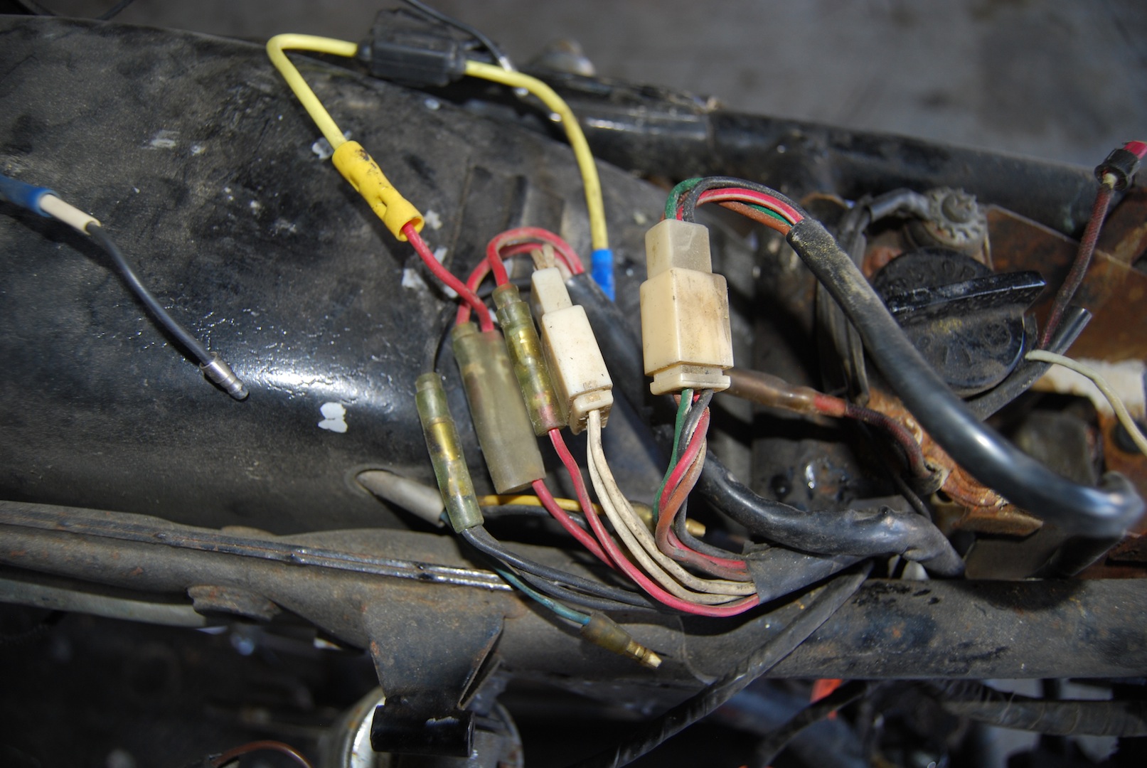
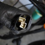
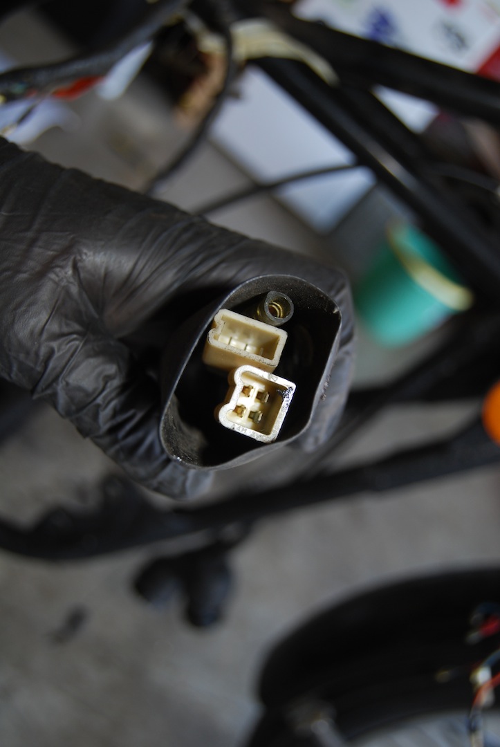
A) A 4-pin connector (red/white, black, green, brown) that goes to the voltage regulator:
-
- Connector going to voltage regulator
-
- Wires running through battery box to voltage reg and rectifier
B) A 3-pin connector (all white) that goes to the rectifier (no specific pics)
C) A red/white wire that goes to the rectifier (see original photo showing all connectors)
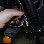
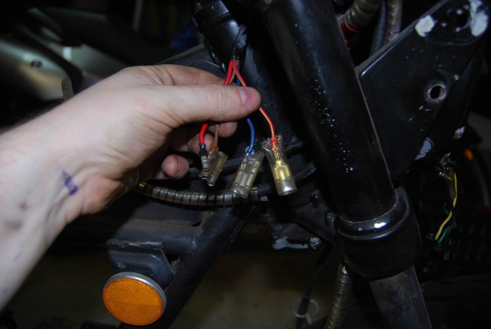
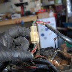
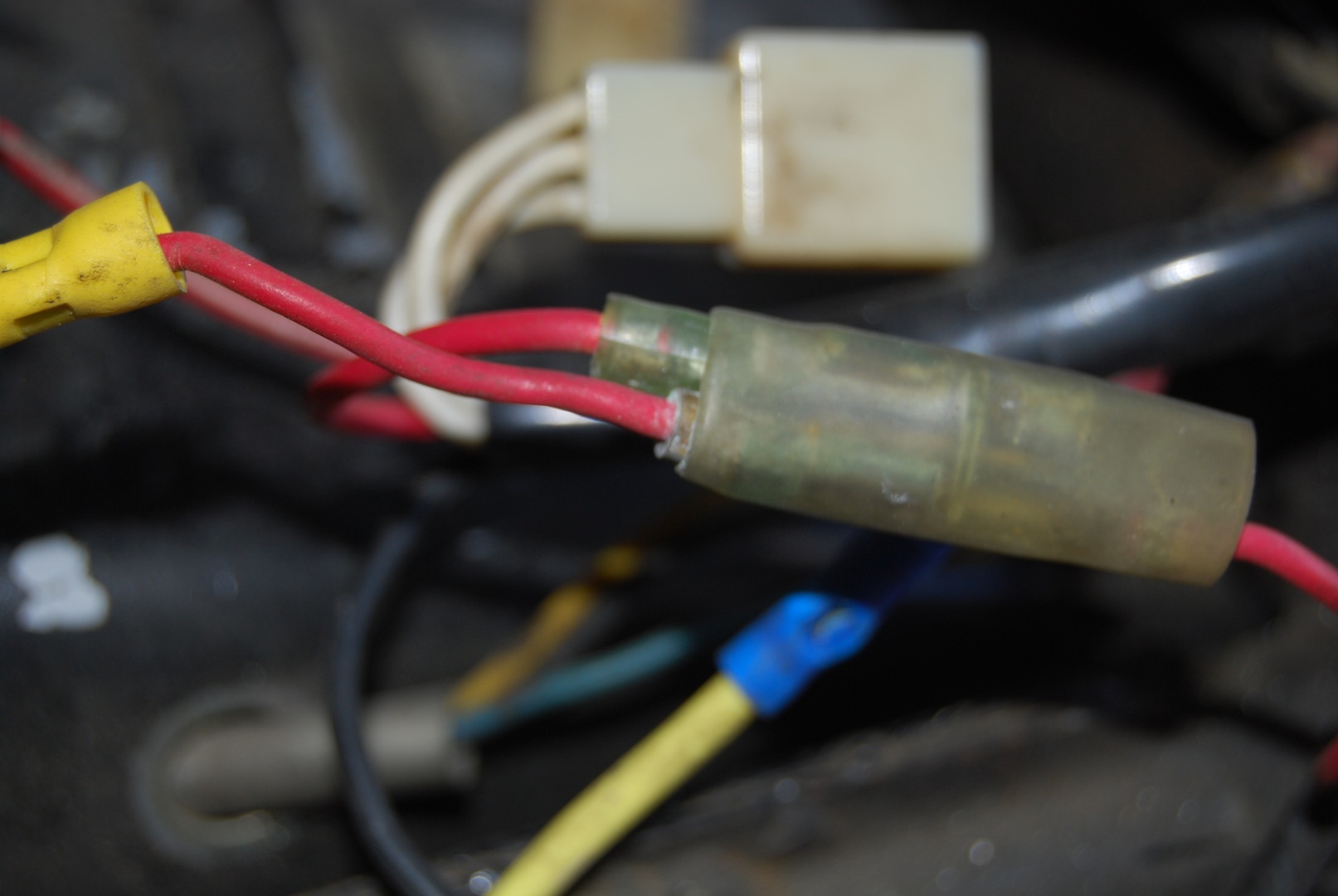
D) A red wire that goes to a junction with 2 other connections: 1) A fused line from the battery, and 2) another line from the rectifier.
-
- Red wire junction. Top left is wire to harness, bottom left is fused wire from battery, bottom right is wire to rectifier.
-
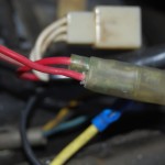
- Closeup of red junction
E) Two black wires that “Y” into 1 that leads to the rectifier.
There is one final black wire that leads from the main harness to an “O” connector on the left side of the battery box. Looks like it grounds the wire to the frame.
Grounded frame wire
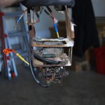
That’s it!! You’ve removed and documented all the main harness connections.
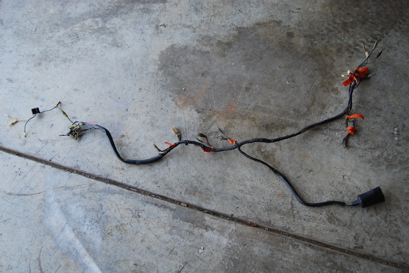
Full harness removed
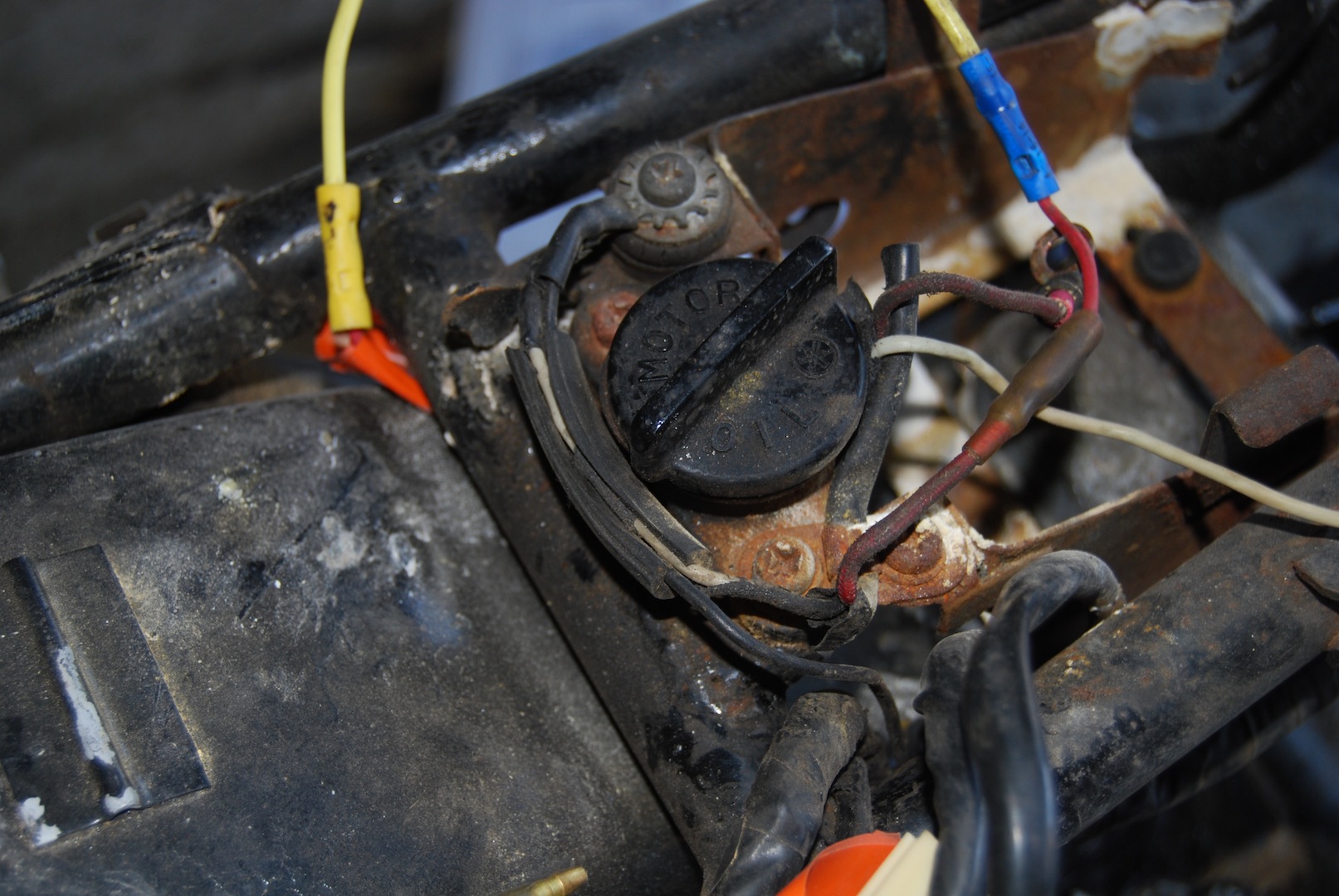
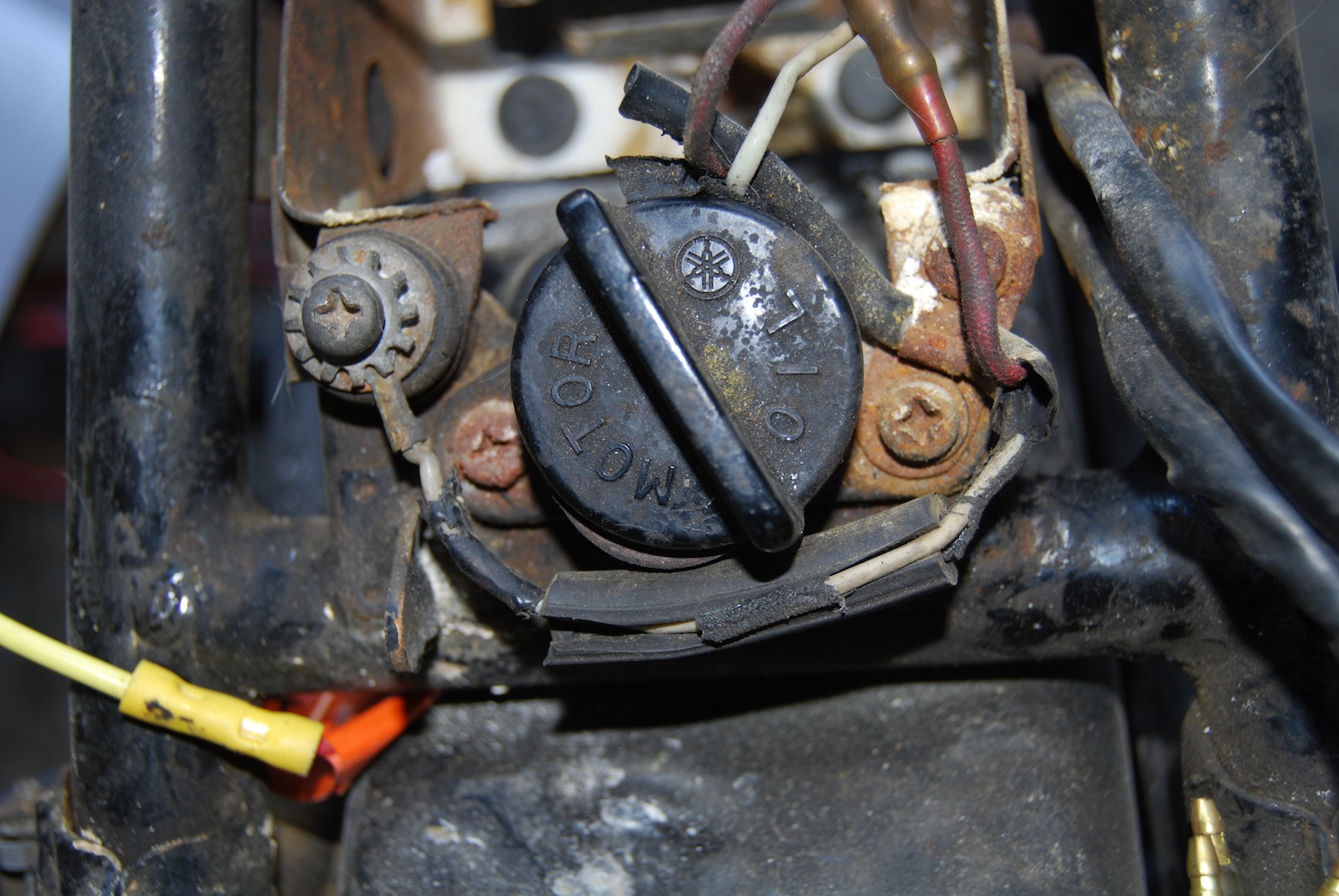
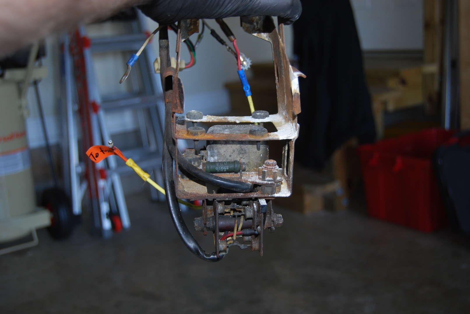
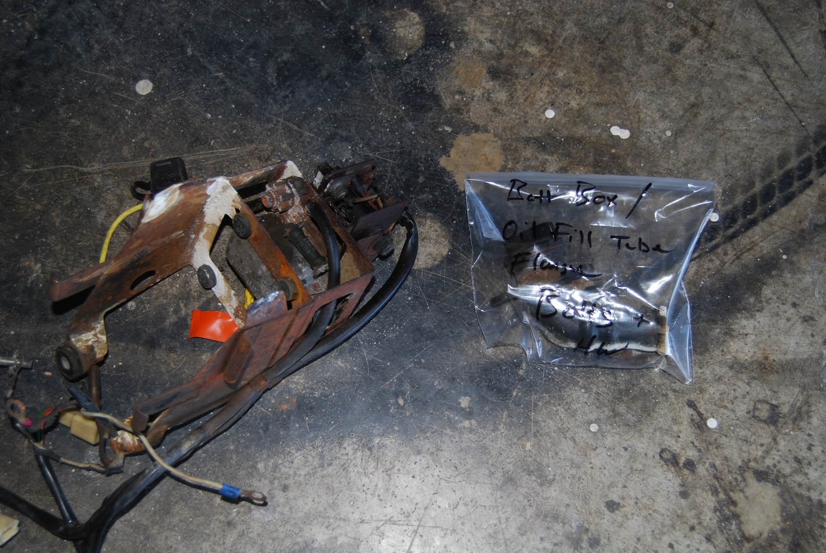
Last step is the battery box. It sits on top of the flange for the oil feed tube. Notice the two bolts on either side of the oil cap. Those need to be removed to remove the battery box. Then you just give the whole box a squeeze inward, and it should detach from the frame slots and pull free, with the rectifier and voltage regulator attached.
-
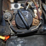
- Oil pipe flange
-
- Battery box wings
-
- Frame slots for battery box
-
- Voltage reg and rectifier
-
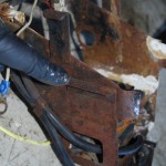
- Pipe and battery box removed
That’s it for now. We’ll worry about removing the rest of the stuff from the rear (lamps, signals, fender, wheel, etc) later.
Upgrades:
After linking my last post regarding the headlamp junctions on the Cafe Racers subreddit, Reddit user Mr_JS had some awesome suggestions.
1) You can purchase a new wiring harness for these bikes (http://www.hvccycle.com/wire-harness.html), but a brand new harness costs $210! I know there’s lots of work getting the length and colors right, but it seems expensive for a bunch of wires and terminals. The suggestion was to make a DIY harness that only has what you need. I know that changes I make to the battery, gauges and handlebar controls are all going to impact the harness. So in an effort to make it as minimal as possible, I’ll likely recreate my own. Most difficult part (I imagine) will be sourcing the correct connectors.
2) Simplify the system as a whole by using a MotoGadget M-Unit and a MotoGadget M-Button. These awesome gadgets simplify communication from the front of the bike to the rear, provide individual solid-state relayed lines, make wiring much easier, and even integrate the flasher itself so you can get really neat flashing control besides just on-off. Check out this video below, I’m definitely adding these to the bike.