
In early 2019 I was approached by a colleague from my days working at the Center for Visualization and Virtual Environments at the UK College of Engineering with some contract work. He was in charge of creating an apparatus capable of quickly and autonomously taking photographs of ancient scrolls from a library in Italy. And not just any photographs, these needed to be high resolution photos from very particular angles that would be fed into a photogrammetry pipeline. This processing would turn a collection of 2D images into a 3D model, and it would be done in a noninvasive manner- turns out physically handling fragile ancient documents is generally avoided 😉 .
After some back and forth discussion, I proposed leveraging an entry-level CNC platform to handle movement of the cameras, and a custom built camera array that would take the place of the router on the CNC machine. This meant the end product would exhibit:
- A scan-able surface area of 750mm x 750mm,
- A custom designed scanner head for carrying up to 5 cameras, mounted at an angle (TBD) sufficient for capturing surface details of the work piece,
- Control software that would allow for interaction with the CNC motors and cameras, and
- A lighting interface to control the illumination of the work piece
Getting Started with UX
The first step after the initial planning phase was to really understand what did and didn’t need to be available to the end user. Whether or not these scanners would be run by the researchers commissioning the work, or by less-technical volunteers at the target library, would largely impact what kind of capabilities needed to be made available. I started with a very simple mock-up to get the ball rolling.
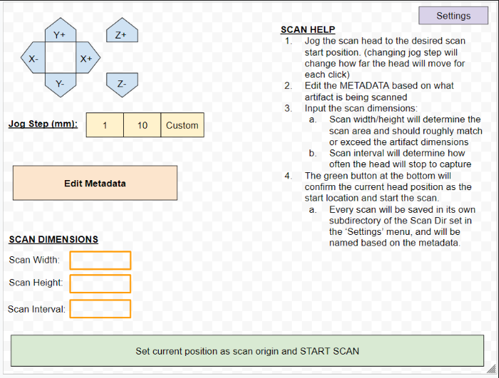
The UX here is pretty straight forward – some simple machine interface controls to move the camera head around and up/down, a couple of options for how far each click of the directional buttons should move the head, a section for metadata (maybe to fill in some identifying info on the work-piece), and details about the scan itself – how wide and high to take photos, and at what intervals photos should be taken (every 5mm, for example). Then simply move the head to where you want to start scanning and hit the big green button at the bottom.
I got immediate feedback – the first pass was fine, but details on the current position of the head, hiding menu options that could potentially crash the head into the work piece (the z-height buttons), and a live feed of the cameras were some desired changes, along with inclusion of some kind of control for the color of the LED lights.
A Functional Overview
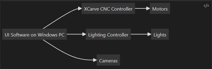
The requirements of the software interface were many and varied, as it had to talk to three different subsystems in a manner that would accomplish complex tasks in a safe, reliable, and timely manner. I divided these efforts into three function blocks:
- Motor Control – To control the motors, the UI software needed to adapt to the expectations of the firmware running on the XCarve CNC Controller attached to the CNC machine. This controller took GCODE commands and turned them into a stream of signals sent to the motors. And so the first major development component was understanding what the CNC controller expected (when to unlock, how to communicate over serial connection, what commands and in what order were expected, etc.).
- Lighting – The lights were a different story. Most LED strips come with a basic remote, but in order to control and select colors from the main software package, I needed to add a microcontroller to the loop, which meant a) some hardware design, and b) some firmware to accept incoming commands from the windows software and turn on/off lights or change colors as needed.
- Cameras – The cameras thankfully didn’t require any interface devices, but they were a bear to get setup. The software and drivers to control these cameras via USB from the windows PC was clunky, and the python API was not well documented. Thankfully the researchers at UK had used the interface before and were able to take my MVP and add the specific bells and whistles they wanted in the end. The most time consuming part for the cameras for me was the creation of the mounts.
Motor Control
The language of CNC is G-code. Thankfully the controller that came with the X-Carve CNC we adapted for use for the scanner had a serial interface that accepted G-Code, and moving the machine was a simple matter of converting the movements we wanted into G-Code and then sending those instructions to the machine. My first iteration involved taking the width, height, and # of desired steps and converting those into G-Code instructions that would be run by the machine:
def GenerateScanGCode(machine, cr, width, height, step):
    print("Width: " + str(width) + " height: " + str(height) + " step: " + str(step))
    s = settings.Settings()
    scanfeedrate = s.sfr
    eolfeedrate = s.eolfr
    floatstep = float(step)
    lines = []
    # Add check here to ensure # of steps will not outrun the bounds of the machine
    num_x_steps = math.ceil(float(width) / floatstep)
    num_y_steps = math.ceil(float(height) / floatstep)
    print("Num X Steps: " + str(num_x_steps))
    print("Num Y Steps: " + str(num_y_steps))
    dwell = "delayn"

    for y in range(num_y_steps + 1):
        for x in range(num_x_steps):
            # Code to take photos or possible dwell in line below
            line = "$J=G91 G21 X" + str(floatstep) + " F" + str(scanfeedrate) + 'n'
            lines.append(dwell)
            lines.append(line)
        line = "$J=G91 G21 X" + str(-floatstep*num_x_steps) + " Y" + str(floatstep) + " F" + str(eolfeedrate) + 'n'
        lines.append(dwell)
        lines.append(line)

    print(lines)
    machine.runCommandList(lines, cr, s.output_dir)
Splitting the code into classes meant we could swap in different machines if need be as long as they implemented the same interfaces. In fact, this approach paid of well because the researchers at UK wrote a simulator class to test the code in the absence of a machine! I implemented a basic event system, and the machine class would run each line of g-code, pausing at the “delay” lines and waiting for the images to be written to the filesystem.
def runCommandList(self, cmdlist, cr, parentDir):
        i = 0
        # This is where some of the metadata will likely be used to change the directory names
        scanDirName = "test"
        baseDir = path.join(parentDir, scanDirName)
        print("Base Directory: " + baseDir)
        if not path.exists(baseDir):
            os.makedirs(baseDir)
        for line in cmdlist:
            l = line.strip()
            if "delay" in l:
                state = self.getMachineState()
                while(state is not 'Idle'):
                   sleep(self.captureWait)
                   state = self.getMachineState()
                cr.capture(str(i), baseDir)
                i = i+1
                continue
            while(path.exists(path.join(baseDir, 'cam' + str(cr.num_cameras - 1) + 'img' + str(i-1) + '.png')) == False):
                print('waiting for: ' + path.join(baseDir, 'cam' + str(cr.num_cameras - 1) + 'img' + str(i-1) + '.png'))
                sleep(self.captureWait)
            self.sendCommand(l)

        self.OnScanningComplete()
For a first-pass effort, it worked well:
Lighting
The lighting components involved a surprising amount of work compared to the motor control. I needed to invent an application interface that the desktop software could use to tell the firmware on a microcontroller which LEDs to enable. Starting downstream, the firmware on the micro (an arduino copycat) was pretty straightforward in it’s capability – loop until you receive a full terminated command, parse the command to figure out if it’s a brightness or color command, and then parse the rest of the data before writing the updated values to the output pins (setting R/G/B values individually for colors, or decreasing overall brightness). Here’s a small snippet of that firmware:
void loop() {
receive();
if(newData == true){
strcpy(tempChars, receivedChars);
parseData();
if(command[0] == 'B') {
setBrightness(brightVal);
}
else if (command[0] == 'C') {
setColor(Rval, Gval, Bval);
}
else{
Serial.println("Unknown Command");
}
newData = false;
}
}
void receive() {
static boolean recvInProgress = false;
static byte i = 0;
char startMarker = '<';
char endMarker = '>';
char rc;
while (Serial.available() > 0 && newData == false) {
rc = Serial.read();
if(recvInProgress == true) {
if(rc != endMarker) {
receivedChars[i] = rc;
i++;
if(i >= numChars) {
i = numChars -1;
}
}
else {
receivedChars[i] = '';
recvInProgress = false;
i = 0;
newData = true;
}
}
else if(rc == startMarker) {
recvInProgress = true;
}
}
}
void parseData() {
char * strtokIndx;
strtokIndx = strtok(tempChars,",");
strcpy(command, strtokIndx);
if(command[0] == 'B') {
Serial.println("Got a brightness command");
strtokIndx = strtok(NULL, ",");
brightVal = atoi(strtokIndx);
}
else if(command[0] == 'C') {
Serial.println("Got a color command");
strtokIndx = strtok(NULL, ",");
Rval = atoi(strtokIndx);
strtokIndx = strtok(NULL, ",");
Gval = atoi(strtokIndx);
strtokIndx = strtok(NULL, ",");
Bval = atoi(strtokIndx);
}
else {
Serial.println("Unknown Command");
}
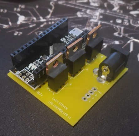
}This also meant I needed to create PCBs. Micro pins aren’t capable of handling the current draw needed by long LED strips, so instead I opted to use Power MOSFETS. These allow the small pins on a micro to control elements that need higher currents than the pin itself can accommodate. At one FET per channel (Red, Green, Blue), a header for connecting the LED strip, and a barrel jack to connect a power supply, this was a pretty straightforward PCB:
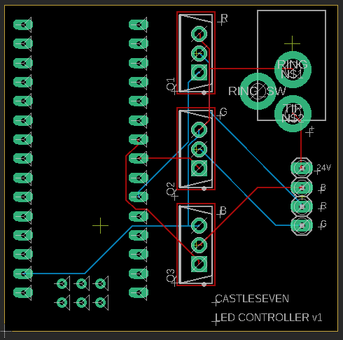
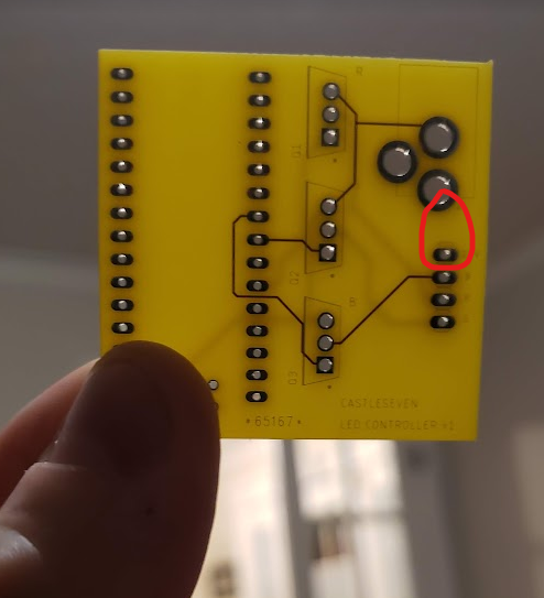
I ordered these from DirtyPCBs, which lets you tag along on larger runs to get PCBs from overseas at steeeeeeep discounts. You get somewhere between 9 and 12 PCBs, and it takes a while, but if those parameters are OK it’s a heck of a deal. Unfortunately my PCBs were missing the trace connecting the power jack to the LED strip, which meant I had to yellow-wire this connection by hand, which wasn’t a terrible deal.
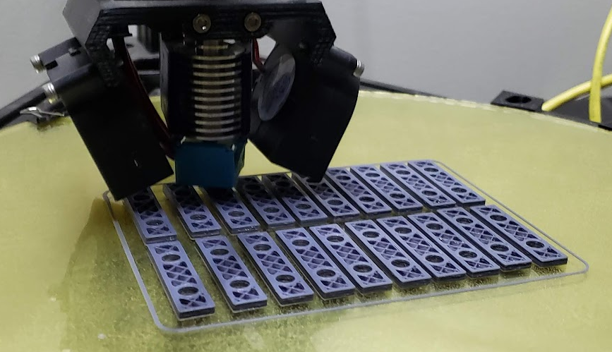
I printed some small brackets that would hold the thickness of the LED strip to the 80/20 aluminum extrusion of the CNC chassis:
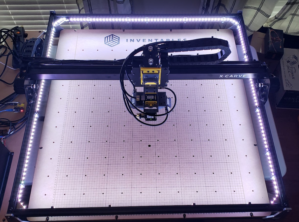
With everything routed and wired, it looked really cool:
Cameras
Like I mentioned above, getting the cameras to work in software was an effort of digesting poorly documented APIs for python control of this particular variety of cameras. These are very popular in CV research, so thankfully some of the team members in the research lab could correct the errors in my implementation. 90% of the time spent on the cameras function block, for me, was an iterative process of figuring out the most appropriate way to attach 5 cameras to a CNC head that provided the coverage needed to successfully create a photogrammetric model of the workpiece. Looking back, the email chains between myself and the lead research at the Vis Center was ~ 70 messages long, full of back-and-forth discussions and drawings and test results of different camera orientations and angles. If you’re just dying to see my MVP for the camera software, it’s showcased here:
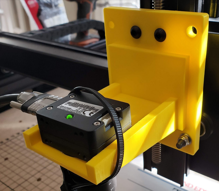
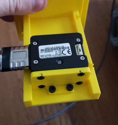
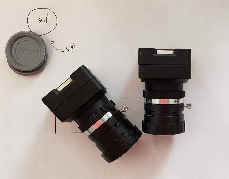
The very first pass effort on the mechanical side of things – can you hold one camera? This involved figuring out two key things. First, the interface to the CNC router mount. And second, the mounting placement for the holes on the camera itself. Demonstrated below is the CNC mount with the camera zip-tied into place:
Next I sorted out the hole pattern for the camera and created an adapter that would hold the cameras at a 90 degree downward facing angle:
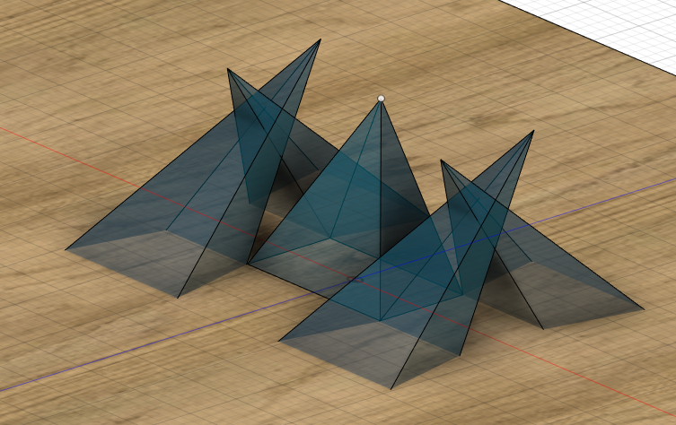
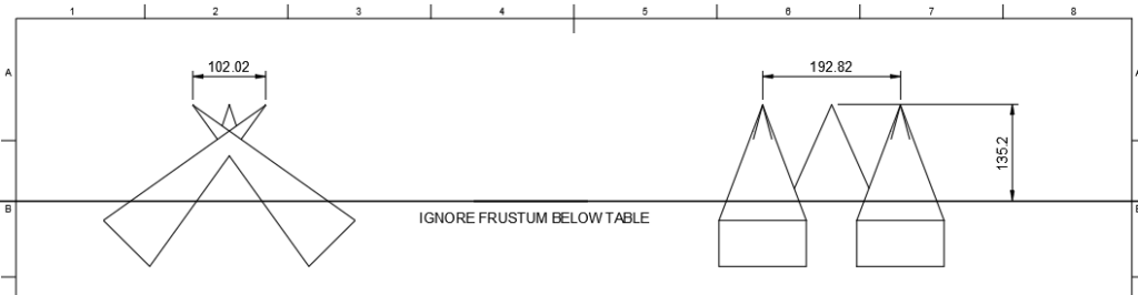
After that came the prolonged discussions about view frustums, 8mm vs 16mm lenses, camera height above the workpiece, and required overlap. This involved a lot of “throw-away” modeling:
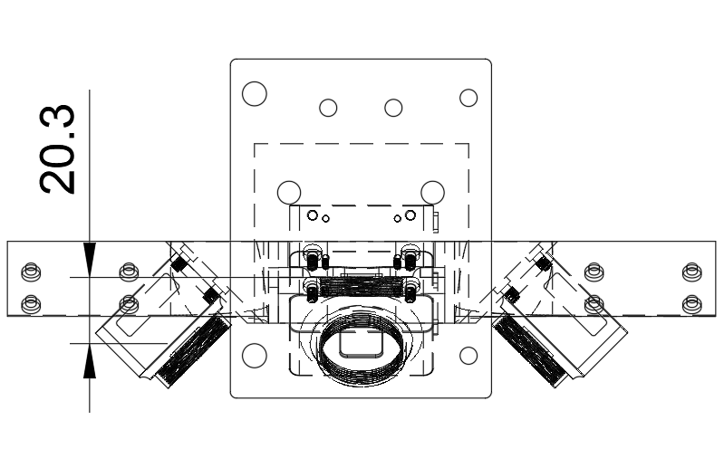
After many iterations back and forth, this is what we landed on:
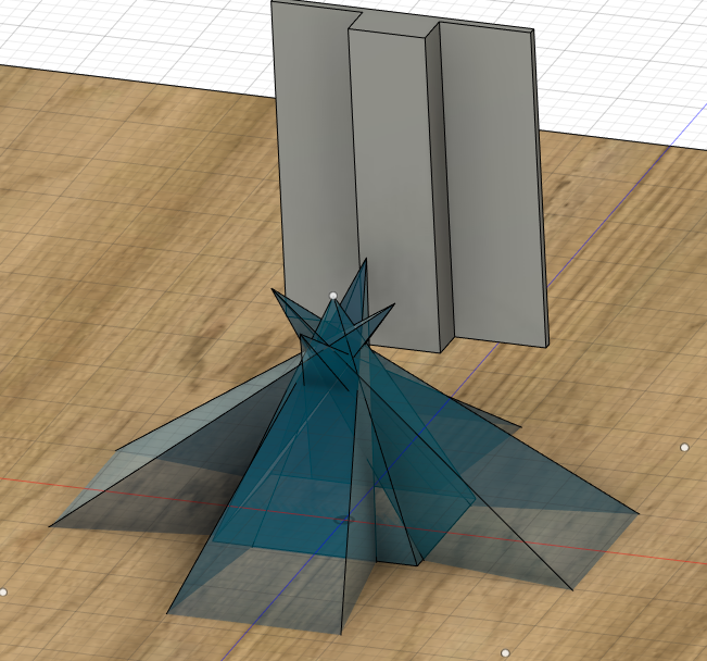
And then this is where simulation meets reality – it’s fine modeling positions from an infinitesimally small point of origin, but in reality, there’s a big camera body and plastics that make mounting some orientations impossible, and that’s exactly what happened:
“To get the exact same layout as the mocked up FOV I sent you this morning will unfortunately be physically impossible given the dimensions of the camera bodies and lenses. I can get them close but I’m going to have to make them non-planar – is that OK?”
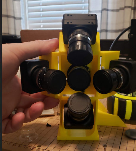
Some more empirical modeling and testing and hundreds of hours of 3D printing later…. and we finally had a workable mount:
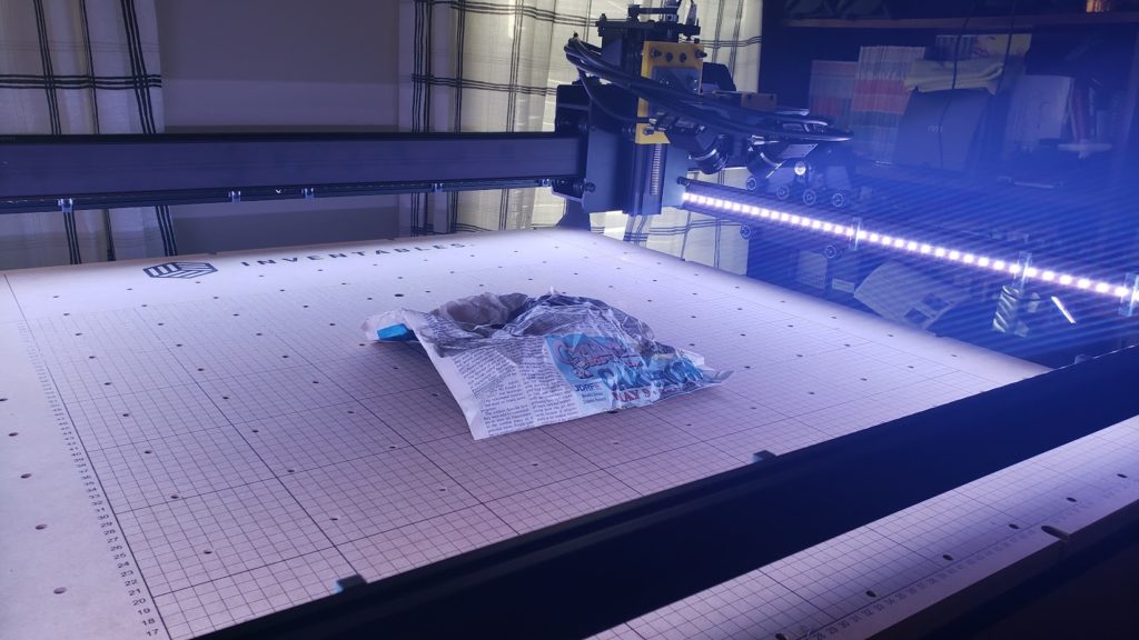
I was so excited to have a working setup, I crumbled some newspaper as a makeshift “ancient artifact” and used the scanner to capture images before running it through MeshRoom), an open-source photogrammetry software (not the same package, as far as I know, that was used in the ultimate deployment of the scanner to Italy).
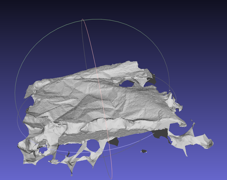
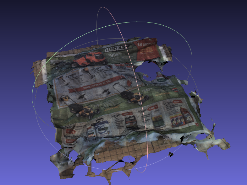
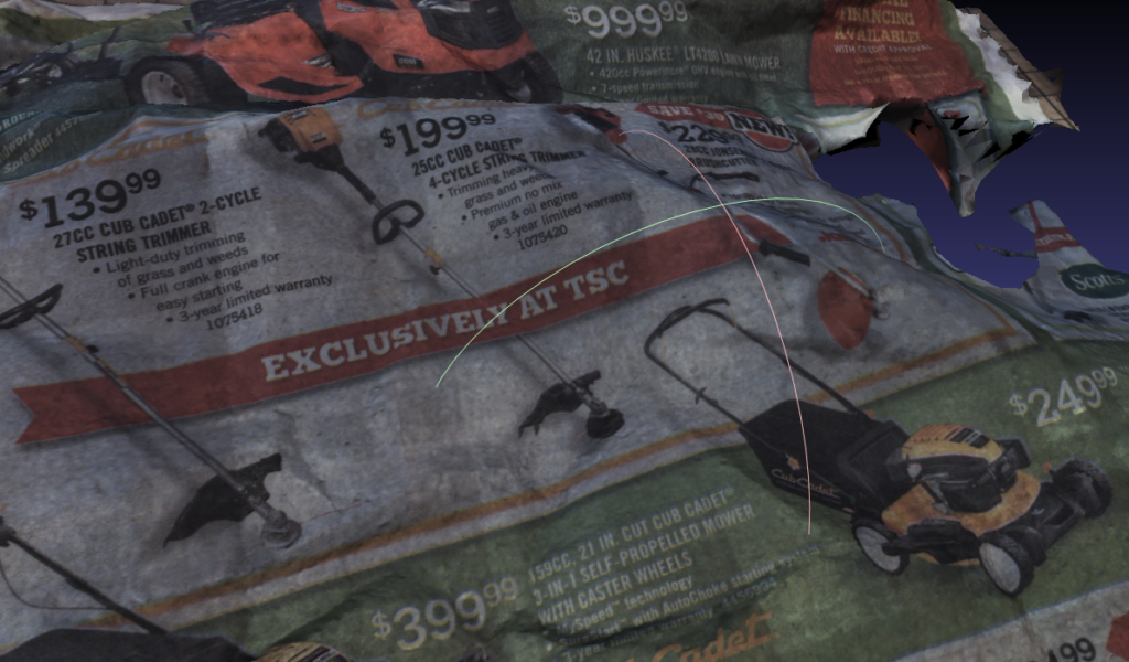
Results
Results were great, and a perfect starting point to fine-tune camera distances above the workpiece, lighting brightness and color, and camera settings for capturing the actual artifacts. A few months later, the UK researchers had taken one of the scanners to Italy and captured images, using the resulting models to drive a list of improvements to be made to the scanner still in the US. I was contracted again to tweak the design of the mounts to accommodate longer lenses and implement more lighting (adding IR LEDs to the head itself).
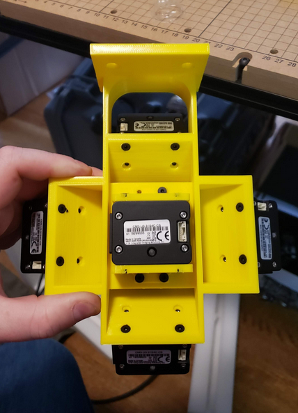
These tweaks resulted in what was lovingly called “The X Mount”:
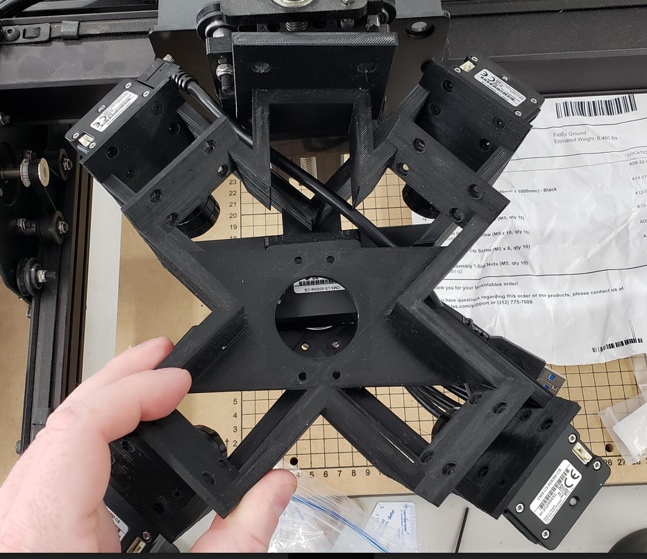
It was a fascinating project and a ton of work in both hardware, firmware, software, CAD, and 3D Printing.